Page 340
REPAIR INSTRUCTIONS, PART 1
399
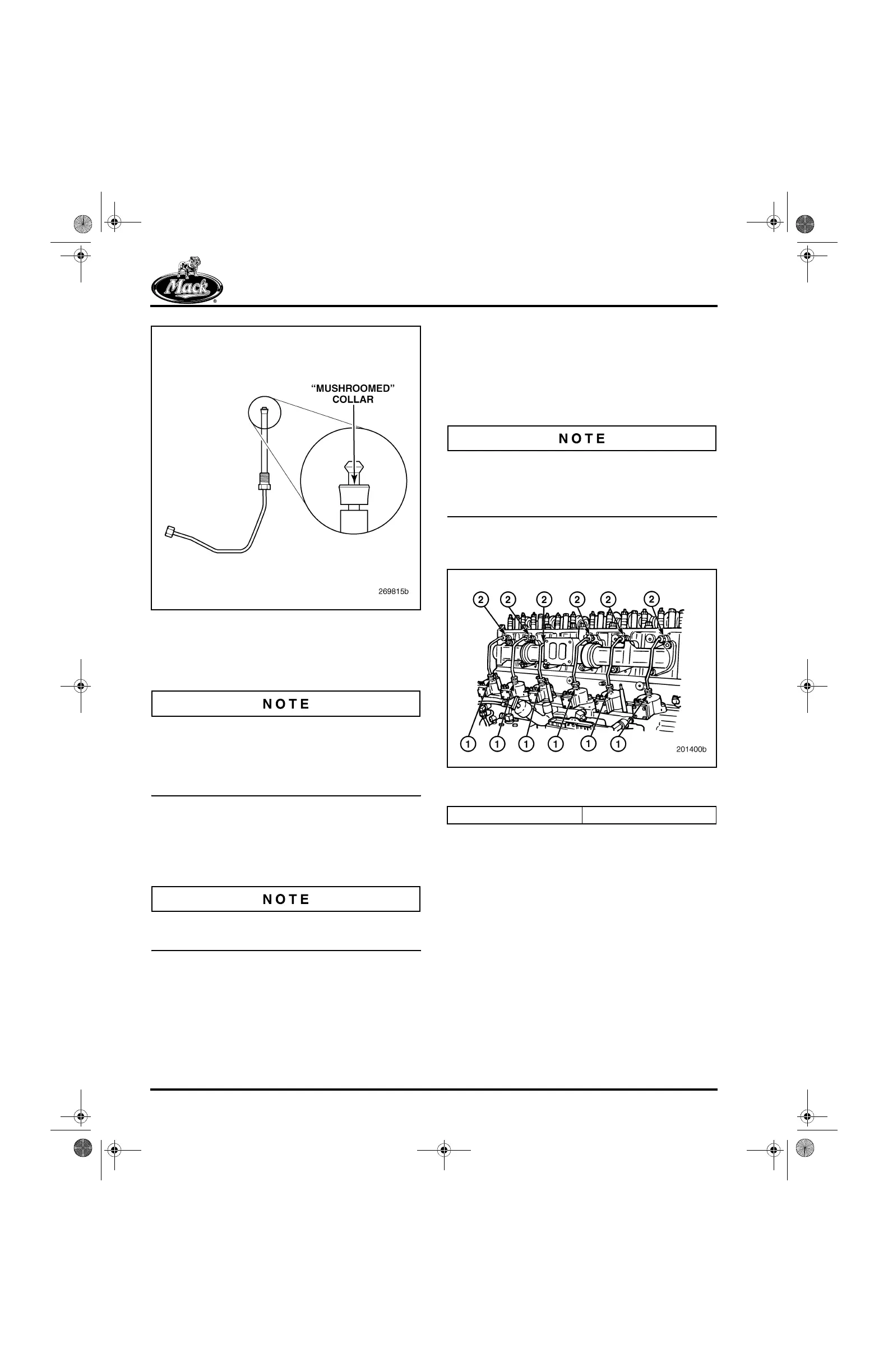
Figure 399 — “Mushroomed” Collar
3. Lubricate the nozzle inlet tube line nut
threads on each assembly before
installation.
Fuel lines should not be bent at any time during
the installation process. If lines are bent, damage
to the fuel line may result. Even bending the line
slightly and then bending it back to its original
shape can damage the line.
4. Install the No. 1 cylinder fuel nozzle inlet
tube assembly into the cylinder head until
light contact is made with the nozzle holder.
Lightly tighten the fuel inlet tube line nut
clamping screw.
The fuel inlet tube assemblies are identical for all
six cylinders.
5. Connect the line at the No. 1 unit pump.
Tighten the line nut to the specified torque,
using torque wrench J 24407, or equivalent.
앫 Line nut at cylinder head: 35 lb-ft
(47 N폷m)
앫 Line nut at EUP: 25 lb-ft (34 N폷m)
An open-ended “crow’s foot” adapter is required
with the torque wrench for installing the nozzle
fuel inlet tube assemblies. Avoid twisting the lines
when tightening the line nuts.
6. Repeat steps 1 through 3 for the five
remaining fuel nozzle inlet tube assemblies.
400
Figure 400 — Fuel Nozzle Inlet Tube Assembly
Installation
7. Place the inner EUP heat shield in position
against the cylinder block. The bottom
flange of the lower EGR heat shield fits
between the EUP heat shield and the block.
8. Install the four capscrews to secure the inner
EUP heat shield and EGR heat shield.
Tighten the capscrews to specification,
15 lb-ft (20 N폷m).
9. Install the outer EUP heat shields and
retaining nuts. Tighten the nuts to
specification, 15 lb-ft (20폷m).
1. EUP Line Nut 2. Fuel Inlet Tube Line Nut
5-111.bk Page 340 Monday, July 10, 2006 2:26 PM