Page 236
REPAIR INSTRUCTIONS, PART 1
GROOVE CUTTING PROCEDURE
1. Place the cutter base on the cylinder head
(Figure 250). Insert the hold-down
capscrews into the appropriate mounting
holes (per application) until the hold-down
capscrews bottom out in the mounting holes.
250
Figure 250 — Cutter Base Alignment
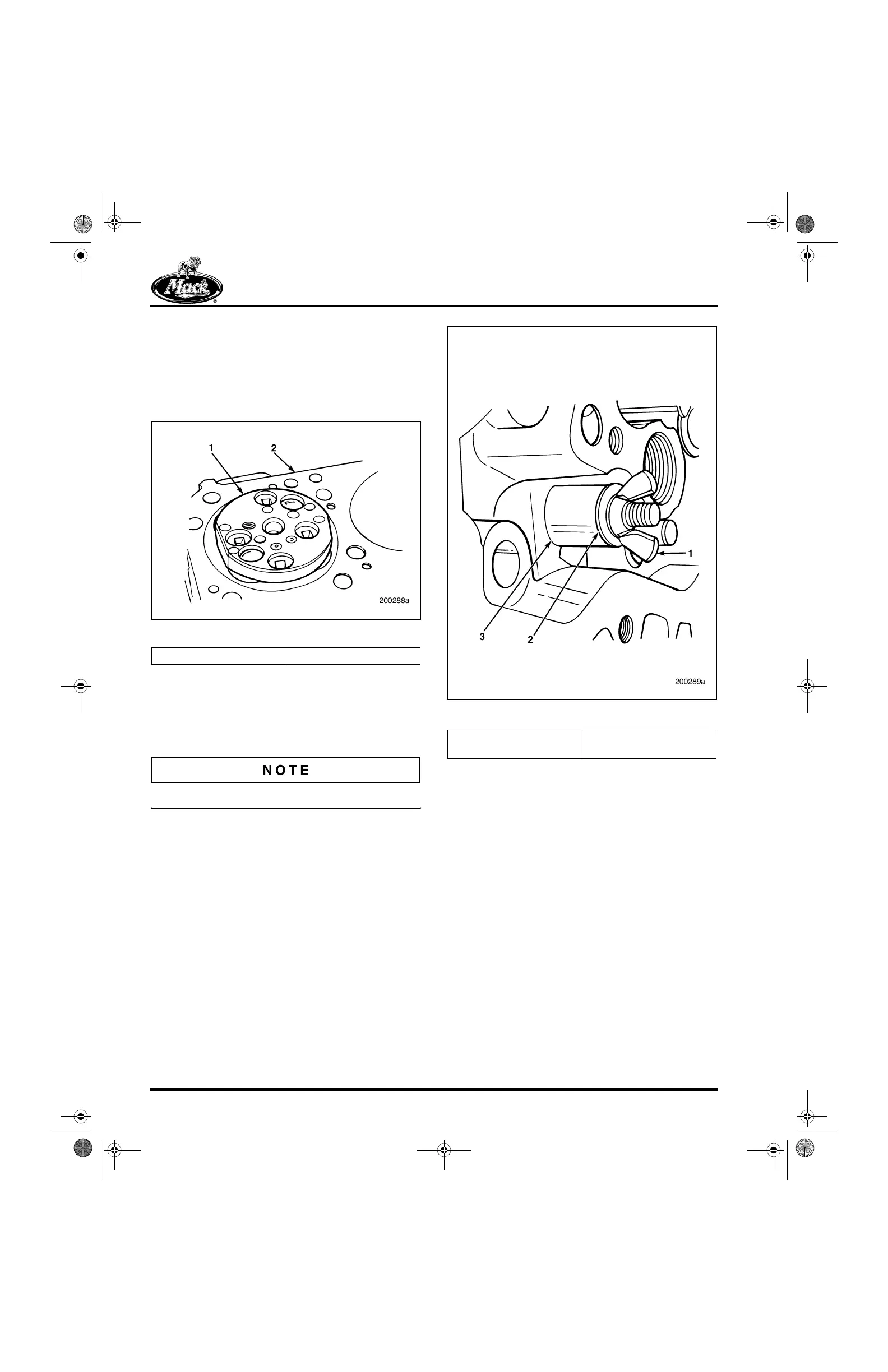
2. Position the cylinder head so the threaded
section of the hold-down capscrews can be
reached as shown in Figure 251. Install the
spacer, washer and wing nut. Lightly tighten
the wing nut.
The cutter base must be free to move.
251
Figure 251 — Cutter Base Attachment
3. Place the alignment fixture over the cutter
base as shown in Figure 252 to ensure
proper positioning. With the fixture in place,
tighten the wing nuts on the hold-down
capscrews. Remove the alignment fixture.
1. Cutter Base 2. Cylinder Head
1. Wing Nut
2. Washer
3. Spacer
5-111.bk Page 236 Monday, July 10, 2006 2:26 PM