REPAIR INSTRUCTIONS, PART 2
Page 377
450
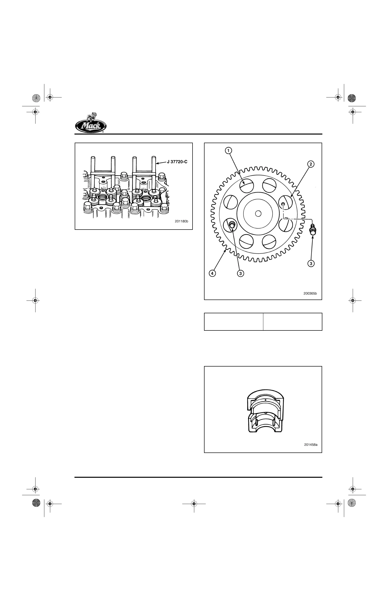
Figure 450 — Valve Lifter (Tappet) Holder Tool J 37720-C
3. If not previously done, rotate the engine in
direction of normal rotation so that the cam
timing marks are positioned at
approximately the 1–2 o’clock position.
4. Remove the two 12-point capscrews that
retain the camshaft thrust washer. The
camshaft may have to be rotated slightly to
make the capscrews accessible through the
openings in the camshaft drive gear. Refer
to Figure 451.
451
Figure 451 — Camshaft Thrust Washer Capscrews
5. Install the camshaft removal/installation tool
J 41682 (Figure 452) in position on the rear
segment of the camshaft, securing it with the
clip to the shaft.
452
Figure 452 — Camshaft Removal/Installation Tool
1. Thrust Washer
2. Openings (8,
Current-Production)
3. Capscrew, 12-Point
4. Camshaft Drive Gear
5-111.bk Page 377 Monday, July 10, 2006 2:26 PM
 Loading...

