Page 66
DESCRIPTION AND OPERATION
The main oil gallery runs along the left side of the
block. A second oil gallery — the valve lifter/EUP
oil supply gallery — runs along the right side of
the block. The valve lifter bores directly intersect
this right-side gallery, while oil is supplied to the
EUP by six passages drilled from the block’s right
side, through the EUP bore and into the adjacent
valve lifter bore. The six holes along the block’s
right side are closed off with pipe plugs.
Both the left- and right-side oil galleries are drilled
from the front and the rear, but do not meet at the
center. Oil is supplied to the valve lifter/EUP oil
gallery through drilled passages from the No. 2
and No. 5 cam bores. An annulus in both the
No. 2 and No. 5 main bearing bores, as well as
the groove in the upper bearing inserts and
grooves around the No. 2 and No. 5 cam
journals, ensure a high volume of oil to the valve
lifter/EUP galleries.
Internal fuel supply and return galleries for the
unit pumps are gun-drilled axially, the full length
of the block’s right side just below the unit pump
mounting flange surface.
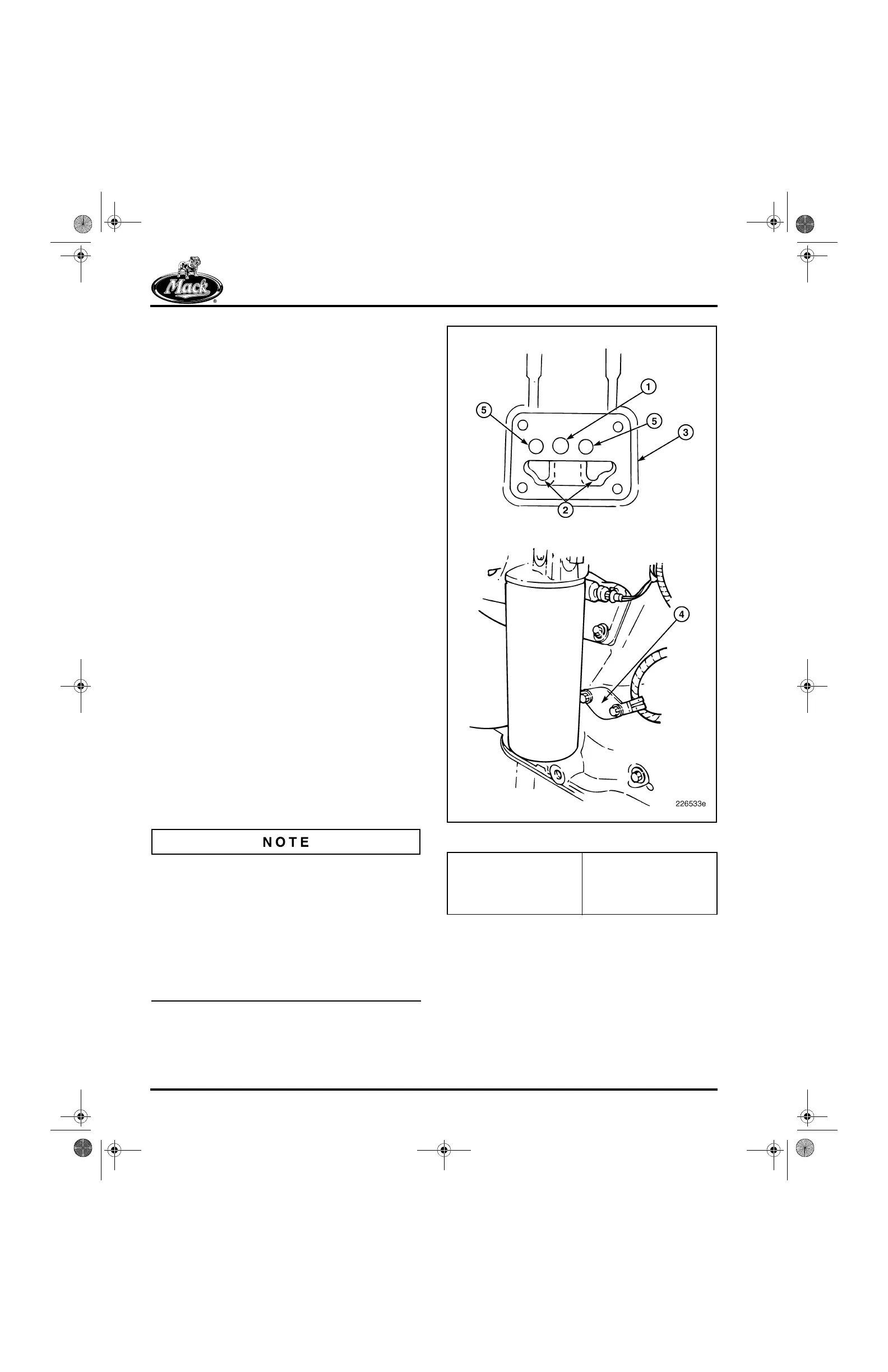
On the left-hand side of the cylinder block at the
center is a four-bolt oil filter pedestal mounting
pad (Figure 75). This pad is cast with two internal
oil drain holes that allow the Centri-Max
®
ULTRA
or ULTRA PLUS drain oil to pass directly into the
crankcase. The two 3/4-inch “as-cast” holes are
visible inside the crankcase on either side of the
No. 4 main bearing bulkhead, between the Nos. 3
and 4 piston cooling nozzles. The external oil
drain port in the cylinder block is no longer used
and is covered with a block-off plate.
The internally drained Centri-Max
®
ULTRA or
ULTRA PLUS filter requires the two internal drain
cavities in the cylinder block. The same cylinder
blocks, however, are used to service engines
having either the non-current externally drained
Centri-Max
®
, or the internally drained
Centri-Max
®
ULTRA or ULTRA PLUS filter
assemblies. When a block is used for an engine
equipped with the externally drained Centri-Max
®
filter, the oil drain cavities are not functional.
75
Figure 75 — Oil Filter Pedestal Mounting Pad
1. Oil Passage — Oil
Pump-to-Oil Cooler and
Filters
2. Internal Drain Holes
3. Mounting Pad (Block)
4. External Oil Drain
Block-Off Plate
5. Oil Passage — Filtered
Oil-to-Main Oil Galleries
5-111.bk Page 66 Monday, July 10, 2006 2:26 PM