REPAIR INSTRUCTIONS, PART 2
Page 399
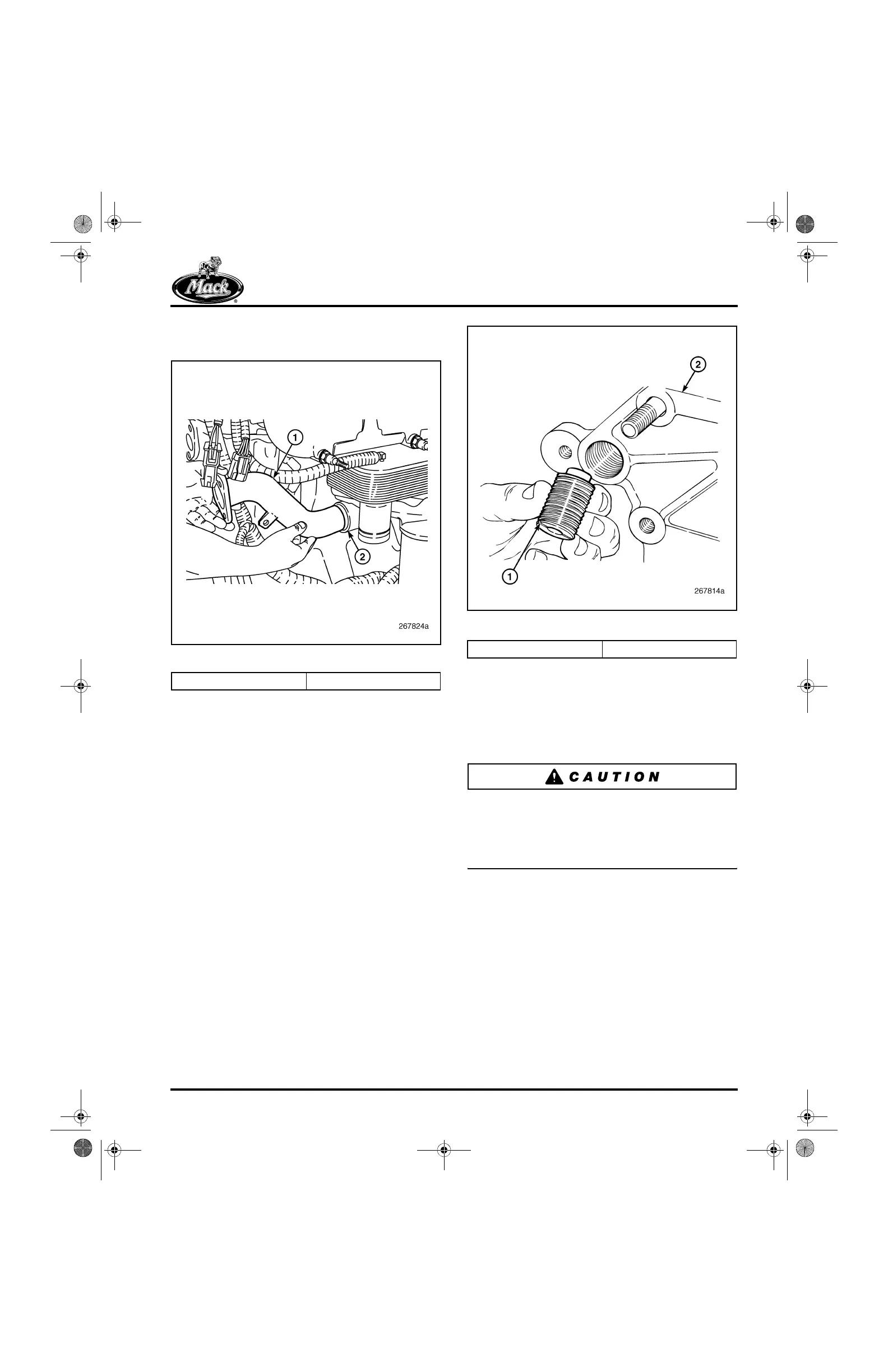
1. Install the water pump coolant inlet tube
from the oil cooler if removed (Figure 478).
478
Figure 478 — Coolant Inlet Tube Removal
2. With the water pump housing positioned on
a bench with the cylinder block/head
mounting surface facing up, position two
new O-rings in the grooves at the coolant
inlet and outlet flanges, respectively. Use
MACK Code 442 grease or any quality
O-ring grease to hold the O-rings in place for
assembly.
3. Stand the housing on edge and from the
front, start the threaded inserts into the
mounting bores at the top of the housing
(Figure 479). Turn them in until the collar of
each protrudes from the back side and the
shoulder is flush with the back side to
0.020-inch (0.5 mm) below flush.
479
Figure 479 — Threaded Insert Installation
4. Again, with the housing standing on edge
and from the front, insert two mounting bolts
and washers into the mid-position bolt holes.
The two mid-position holes are slightly
smaller to serve as pilot holes for
installation.
The water pump cartridge assembly and water
pump housing mounting bolts should not be
lubricated before installation. Instead, apply
thread sealing compound to all cartridge
assembly and housing bolts.
5. Place the housing in position at the front of
the cylinder block (Figure 476) and start the
mid-position bolts into the block, far enough
to secure the housing from falling. The
housing should be free to move slightly back
for installation of the engine lifting bracket in
the following steps.
6. Place the engine lifting bracket in position
(bend angle facing forward) between the
housing and cylinder head (Figure 477).
Make sure the bracket mounting holes clear
and slip into position on the insert collars.
1. Pump Inlet Tube 2. Oil Cooler
1. Threaded Insert 2. Pump Housing
5-111.bk Page 399 Monday, July 10, 2006 2:26 PM