Page 196
REPAIR INSTRUCTIONS, PART 1
In some cases, the H-ring remover tool may not
position the collet far enough into the H-ring to
provide proper engagement for removal. If this
situation occurs, remove 0.375 inch (9.5 mm) of
the threads by grinding or cutting them down;
remove any burrs. This will allow the tool to be
positioned further into the lifter bore.
2. Inspect the cylinder block lifter bore and
place a new standard size H-ring onto the
top of the bore. The H-ring should be a
press-fit. If it is a slip-fit, an oversize H-ring is
required. Determine the oversize as follows:
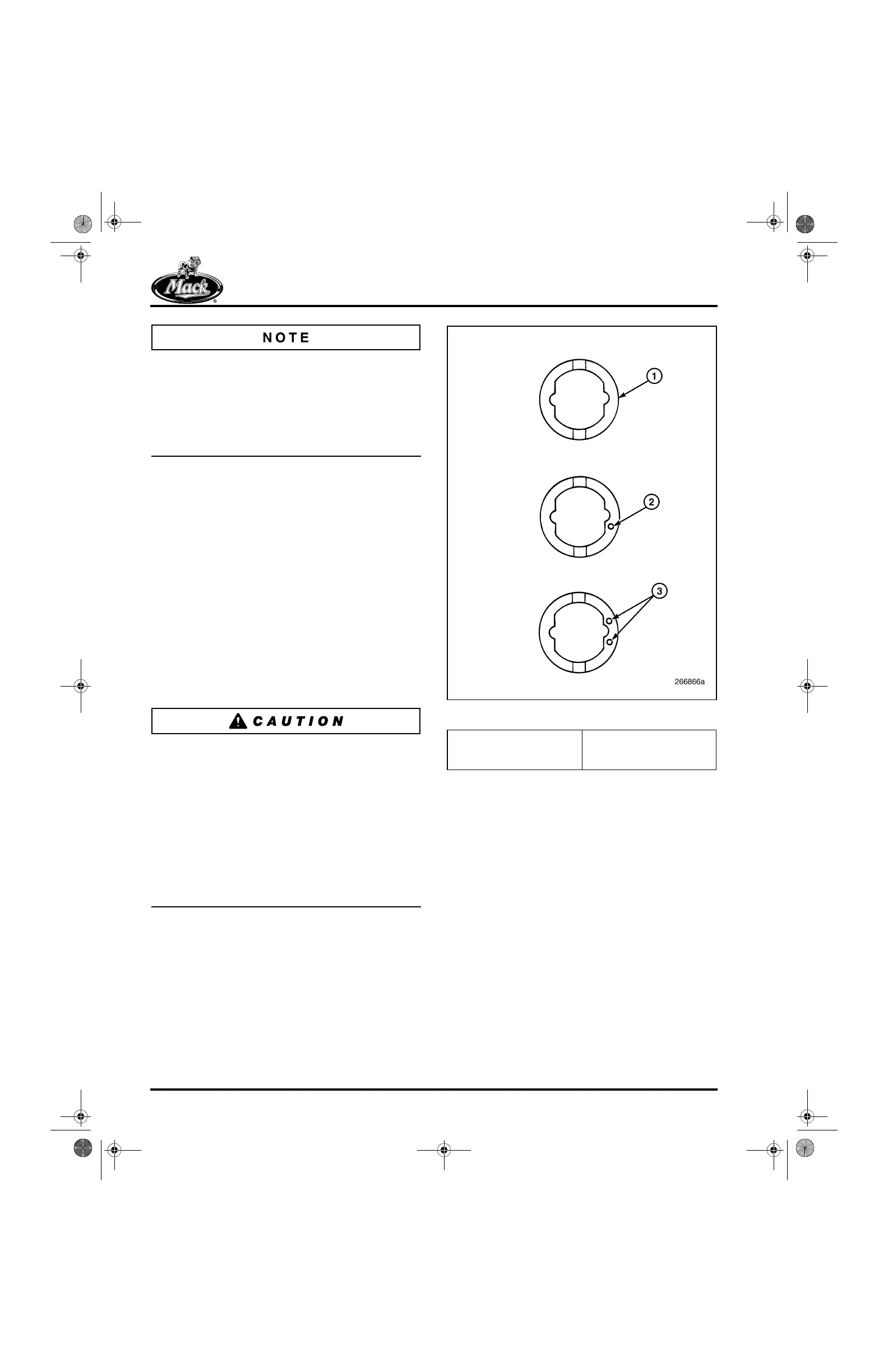
앫 Check the fit of a new “P2” H-ring
(+0.0015 inch [+0.0038 mm] oversize).
If it is a press-fit, install it. The P2 can
be identified by a single dot formed into
the bottom surface next to the flat as
shown in Figure 195.
앫 If the P2 is slip-fit, install a new “P3”
H-ring (+0.0030 inch [+0.076 mm]
oversize). The P3 can be identified by
two dots formed into the bottom
surface.
An oversized H-ring is to be used only when the
bore in the cylinder block is oversize. To use an
oversize H-ring in an undamaged standard size
bore will result in a press-fit that is too tight,
causing the H-ring to collapse. A collapsed H-ring
will eliminate free movement of the valve lifter or
prevent it from being installed. For a proper
press-fit, the H-ring-to-bore interference fit should
be within the range of 0.0006–0.0020 inch
(0.015–0.051 mm). An interference fit less than
the 0.0006-inch minimum will result in the H-ring
dislodging or turning in the block bore.
195
Figure 195 — Available H-RIng Sizes
3. If the lifter bore appears OK (will support the
interference fit of the H-ring), clean the bore
and dislodged H-ring (or new H-ring, if
required) with Loctite
®
Primer T. Then apply
Loctite
®
RC/609 to the bore and to the
H-ring outside surface.
4. Use service tool J 41683 to install the H-ring.
This tool pilots into two lifter bores at the
same time to properly align and install the
H-ring. If the proper interference fit has been
maintained, resistance should be felt as the
H-ring is driven into the bore. Refer to
Figure 196 and Figure 197.
1. Standard (No Dots)
2. 0.0015-Inch Oversize
(1 Dot)
3. 0.0030-Inch Oversize
(2 Dots)
5-111.bk Page 196 Monday, July 10, 2006 2:26 PM