Page 212
REPAIR INSTRUCTIONS, PART 1
BLADE-TYPE DOWEL PIN INSTALLATION
Refer to either Figure 217 or Figure 218.
1. Position the round end of the blade-type
dowel pin into the dowel pin hole in the
cylinder block. The blade end must be
aligned vertically (up and down) with the
block for the rear position and at
approximately a 51-degree angle for the
front position.
2. Using a hammer, drive the dowel pin into the
block until the shoulder of the pin is flush
with the cylinder block surface.
3. Measure the pin protrusion at both the front
and the rear blade pin locations. Adjust pin
height to match these dimensions, if
required.
앫 Front location:
— Blade Pin 0.77 inch (19.56 mm)
앫 Rear location:
— Blade Pin 0.91 inch (23.11 mm)
217
Figure 217 — Pin Angle Alignment (Front)
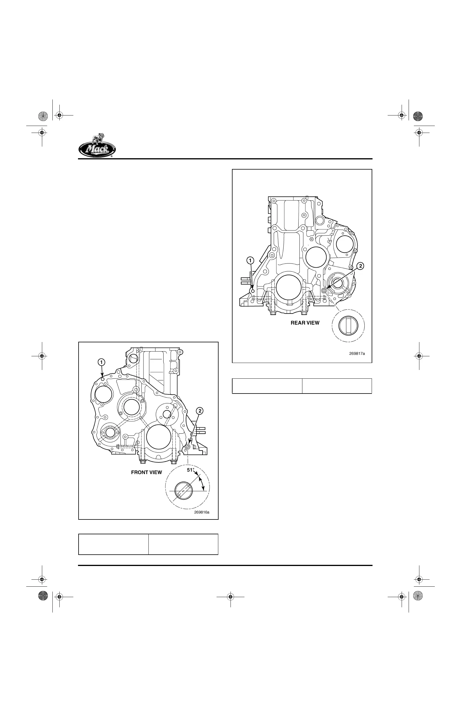
218
Figure 218 — Pin Angle Alignment (Rear)
1. Round Locating Pin 2. Blade Locating Pin
(Approximately
51-Degree Angle)
1. Round Locating Pin 2. Blade Locating Pin
(Vertical)
5-111.bk Page 212 Monday, July 10, 2006 2:26 PM