Page 244
REPAIR INSTRUCTIONS, PART 1
1. Clean any carbon buildup from the removal
chamfer in the valve insert.
2. Attach the collet, PT6390-4, to the T-handle
and shaft assembly.
3. Position the collet in the valve seat insert so
the ridge of the collet will grip the chamfer on
the inner upper edge of the insert
(Figure 262). Turn the T-handle to fully
expand the collet.
262
Figure 262 — Collet Positioning
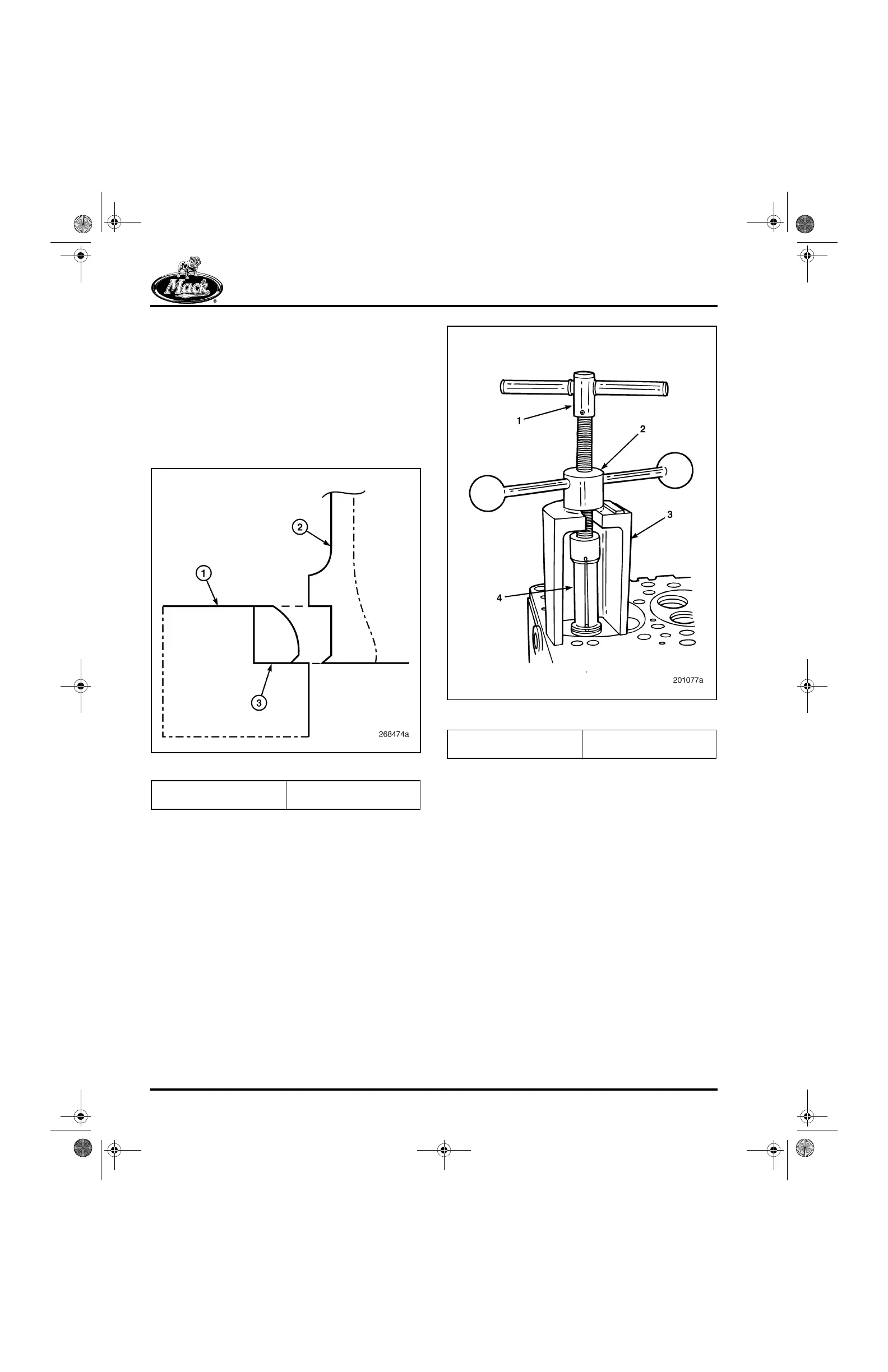
4. Position the lifting bridge under the crank
handle as shown in Figure 263. Turn the
crank handle clockwise to remove the insert.
5. Release the insert from the collet by slightly
turning the T-handle.
263
Figure 263 — Removing Valve Insert
1. Cylinder Head
2. Collet
3. Valve Seat Insert
1. T-Handle
2. Crank Handle
3. Lifting Bridge
4. Collet
5-111.bk Page 244 Monday, July 10, 2006 2:26 PM
 Loading...

