REPAIR INSTRUCTIONS, PART 1
Page 281
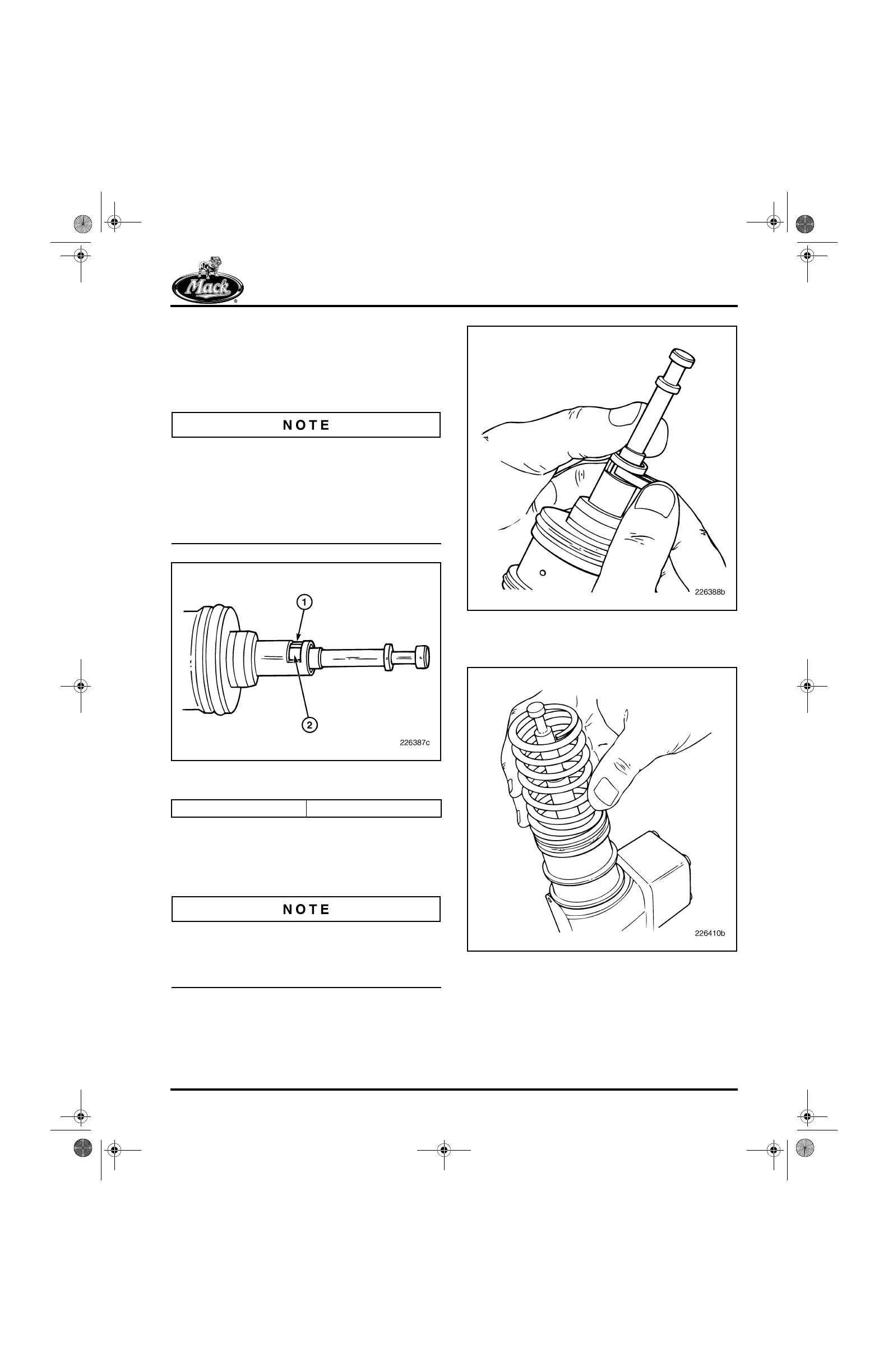
2. Pull the plunger out of the unit pump bore
until the gold portion of the plunger is visible
through the retaining clip slot. The shoulder
of the plunger (where the silver-colored and
gold-colored areas meet), will just align with
the bottom of the unit pump housing.
To avoid possible contamination or damage to
the plunger, do not remove the plunger
completely from the unit pump. If the plunger is
inadvertently removed, dip it in clean fuel and
carefully reinstall it into the unit pump bore. Then
check for smooth, free movement of the plunger
in the unit pump bore.
313
Figure 313 — Gold-Colored Plunger Surface, Behind
Retaining Clip Slot
3. With the plunger pulled from the unit pump
bore as described in step 2, slide the
retaining clip into place. The flat side of the
clip goes into the retaining clip slot.
The plunger must be positioned as described in
step 2 when the clip is installed, or reassembling
the unit pump spring and spring seat will be
difficult, if not impossible.
314
Figure 314 — Plunger Retaining Clip Installation
4. Place the spring onto the unit pump body.
315
Figure 315 — Plunger Spring Installation
5. Install the spring seat (flat side against the
spring) with the larger hole of the spring seat
keyhole opening over the plunger foot.
6. Slide the spring seat so that the plunger foot
goes into the smaller, center hole of the
keyhole slot.
1. Retaining Clip Slot 2. Gold-Colored Surface
5-111.bk Page 281 Monday, July 10, 2006 2:26 PM