Page 300
REPAIR INSTRUCTIONS, PART 1
5. Align the flywheel housing on the dowels
and position it flush against the cylinder
block surface. Refer to Figure 339.
339
Figure 339 — Positioning Flywheel Housing
6. Install the flywheel housing mounting
capscrews and tighten them finger-tight.
7. Tighten all flywheel housing capscrews to
the specified torque, 170 lb-ft (230 N폷m),
using torque wrench J 24407, or equivalent.
RUNOUT
With the machined dowel method of installation,
flywheel housing runout is well within the old
service specification of 0.010 inch (0.254 mm)
Total Indicated Runout (TIR), when checked with
an alignment bar through the cylinder block main
bearing bores. However, when checking flywheel
runout using a dial indicator on the crankshaft
rear flange or the flywheel, results may exceed
0.010 inch (0.254 mm) due to factors such as
crankshaft movement within the bearing
clearances and other variables.
The dial indicator is the only method which can
be used at this stage of assembly (with
crankshaft in place). The machined dowel
method requires that crankshaft and piston
assemblies be removed.
Flywheel housing runout specifications are as
follows:
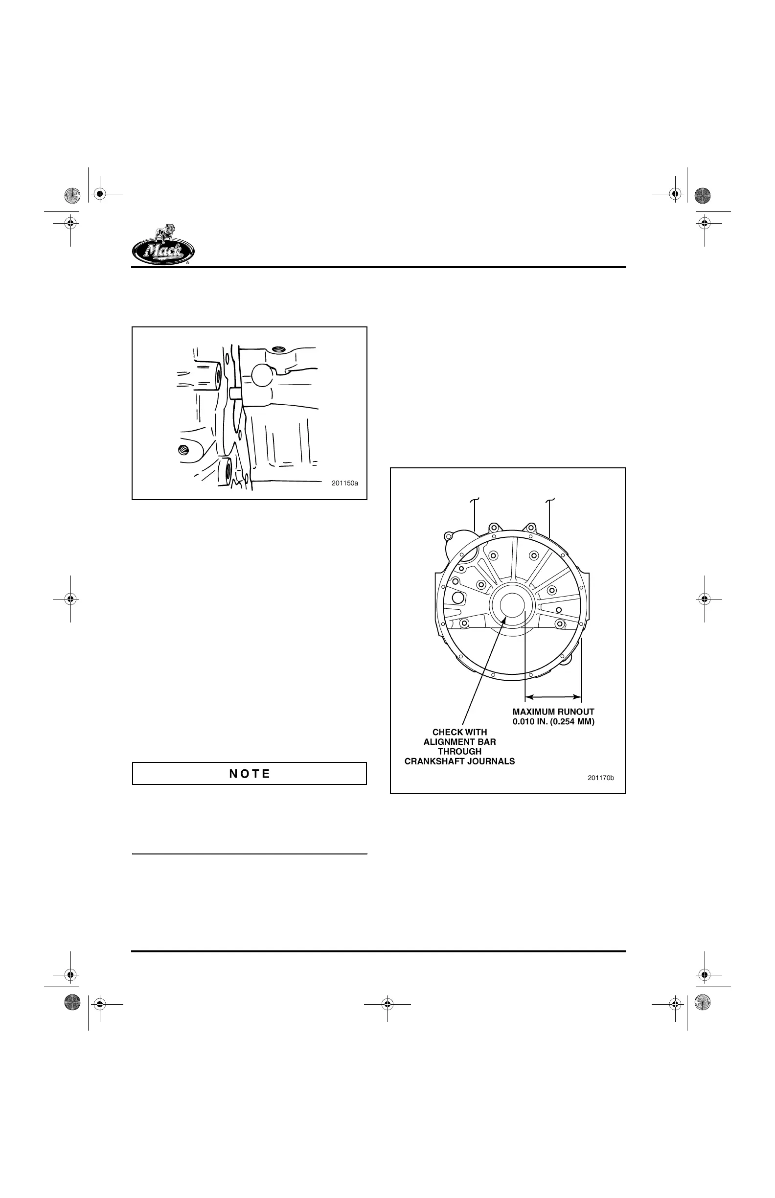
앫 Runout checked with an alignment bar
installed through the cylinder block main
bearing bores: 0.010 inch (0.254 mm) TIR
maximum. Refer to Figure 340.
앫 Runout checked with a dial indicator
(PT5035 with Z adapter PT5035-1) mounted
on the crankshaft rear flange or flywheel as
shown in Figure 341 is 0.020 inch
(0.508 mm) TIR maximum. Using this
method, the runout specification is higher
due to crankshaft movement within bearings
and other variables.
340
Figure 340 — Flywheel Housing Runout Check with
Alignment Bar
5-111.bk Page 300 Monday, July 10, 2006 2:26 PM