REPAIR INSTRUCTIONS, PART 2
Page 375
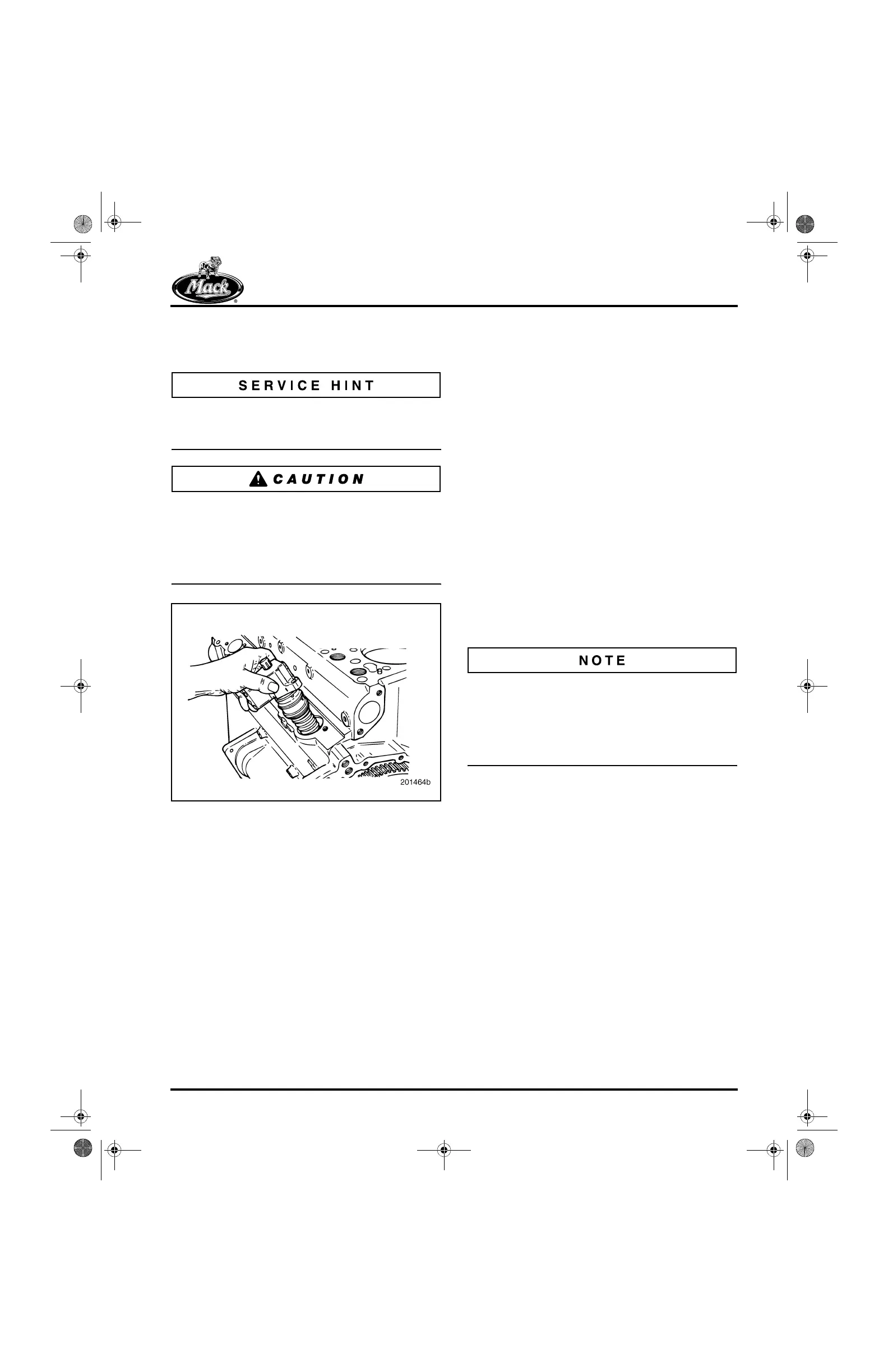
2. Generously lubricate EUP O-rings with clean
engine oil and install the EUP into the
cylinder block (Figure 449).
Minimize oil above the top O-ring to avoid
weepage of excess oil (trapped above the top
O-ring) onto the cylinder block.
To avoid O-ring damage, the cam lobe must be
positioned with the base circle UP prior to
installation of each EUP. Engine barring tool (tool
No. J 3857-A) MUST be used to rotate the
engine. DO NOT use the starter to rotate the
engine.
449
Figure 449 — Unit Pump Installation
3. If not previously done, inspect each EUP
hold-down bolt hole in the engine block for
rusty or damaged threads. Clean or tap
block bolt holes to remove rust or dirt as
required. Use an M10 x 1.5 bottom tap.
4. Install new EUP hold-down bolts and lightly
lubricate the threads and underside of the
bolt head with clean engine oil prior to
installation. Tighten bolts evenly to draw the
EUP into the cylinder block. Tighten the
screws to 60 lb-ft (81 N폷m).
5. Reinstall the injection line and torque to
specification as follows:
앫 Line nut at cylinder head: 35 lb-ft
(47 N폷m)
앫 Line nut at EUP: 25 lb-ft (34 N폷m)
6. Reinstall the harness wire connections at
the EUP terminals and tighten to
specification, 13 lb-in ± 2 lb-in
(1.5 ± 0.2 N폷m). Do not bend the wire
terminals down after installation.
If an EUP has been replaced with a new or
remanufactured unit, the replacement unit must
be calibrated as described under “Electronic
Pump Calibration” in the ENGINE SETUP AND
ADJUSTMENTS section. This will ensure
optimum engine performance.
7. Reinstall both the EGR hot and cool tubes
(AC engine only).
8. Reinstall the heat shields.
5-111.bk Page 375 Monday, July 10, 2006 2:26 PM