REPAIR INSTRUCTIONS, PART 2
Page 393
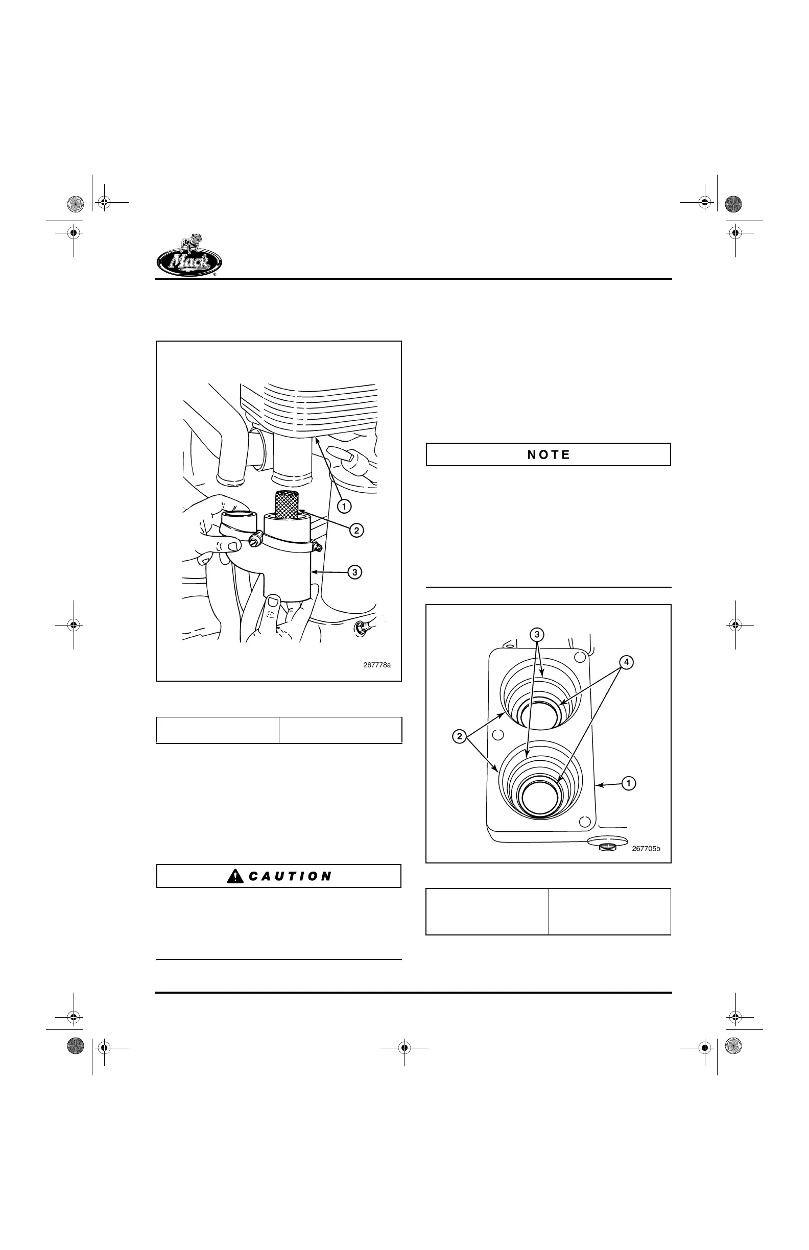
3. Loosen the clamp securing the Y-hose to the
oil cooler inlet port and remove the hose and
filter screen (Figure 468).
468
Figure 468 — Y-Hose, Coolant Screen and Oil Cooler
Inlet
4. Remove the screen from the hose. Clean
the screen and inspect for tears or other
damage. Replace the screen if required.
5. Place the screen in position in the Y-hose.
6. With the clamps positioned on the Y-hose,
install the hose on the oil cooler inlet port.
Tighten the clamp to specification.
Use care not to slide the Y-hose so far onto the
oil cooler inlet port that it blocks the bypass
coolant flow circuit. If the bypass circuit is
blocked, coolant can be forced out of the
expansion tank.
7. Slide the bypass tube into position between
the water pump housing and the inlet
manifold.
8. Connect the tube to the Y-hose and secure
with the clamp tightened to specification.
THERMOSTAT HOUSING INSTALLATION
1. Check to see that the stainless steel wear
rings/shields are properly installed in the
thermostat housing (Figure 469).
If the wear rings/shields are not in place, the
thermostats can wear into the aluminum casting
of the thermostat housing. If the wear
rings/shields become dislodged or out of position,
they can be replaced, or if necessary, crimped to
attain a tight fit, and then reinstalled. The shields
have a very slight press-fit to the bore. An
installation tool is not used. Use finger pressure
to push each shield to full seating.
469
Figure 469 — Wear Rings Installed
1. Oil Cooler
2. Coolant Screen
3. Y-Hose
1. Thermostat Housing
2. Thermostat Rubber Seal
Bore
3. Thermostat Barrel Seal
Bore
4. Wear Rings/Shields
(Pressed In)
5-111.bk Page 393 Monday, July 10, 2006 2:26 PM