REPAIR INSTRUCTIONS, PART 2
Page 395
The seals attached to the thermostats provide
total sealing for the housing-to-coolant manifold
joint. No other sealant is required.
472
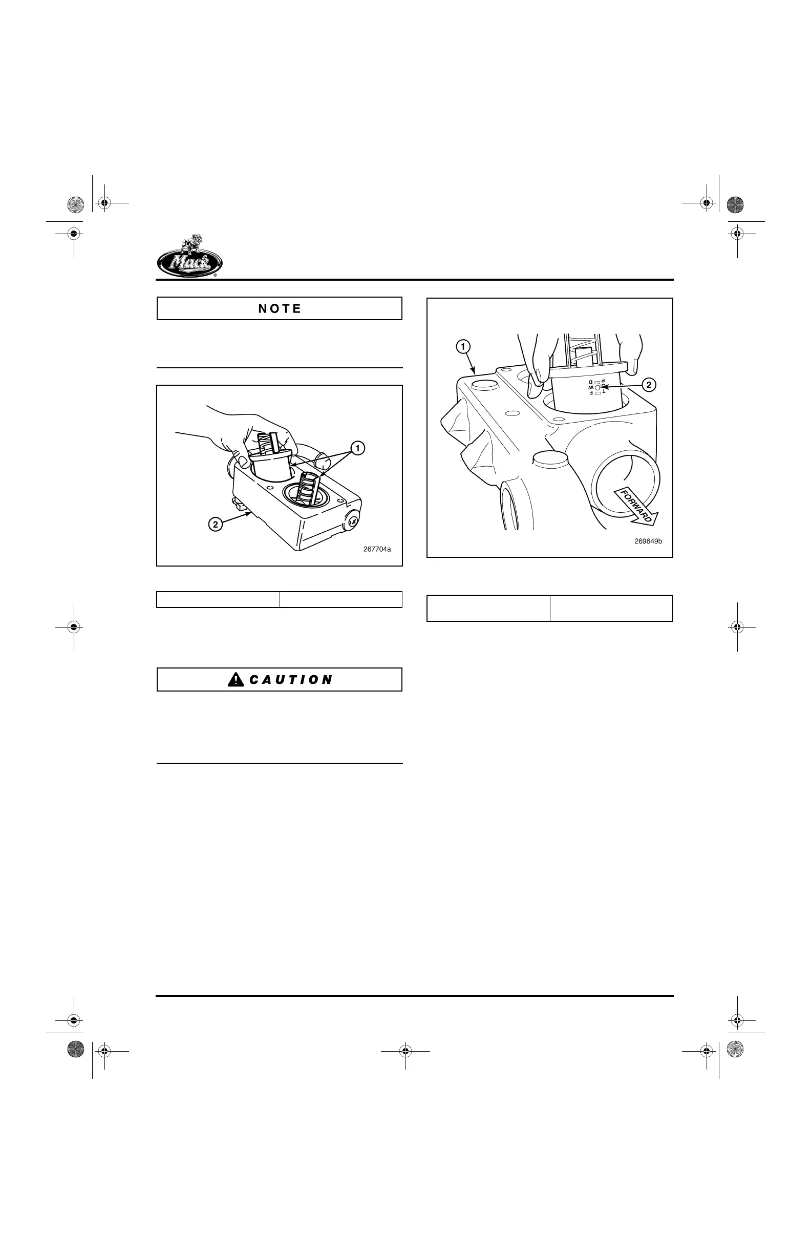
Figure 472 — Thermostat Positioning
4. Position the thermostats with the ball check
valves facing toward the front of the
assembled engine.
Make sure the ball check valves on the
thermostats are facing forward. Proper
positioning of the ball check valve is critical for
proper de-aeration of the cooling system and
proper and complete coolant fill.
473
Figure 473 — Thermostat Positioning on Dual
Thermostat Housing
5. Position the housing assembly on the
coolant manifold mounting surface and
install the three mounting capscrews
(Figure 466). Tighten the capscrews to
specification.
6. Install the cab heater and optional fuel
heater coolant return hoses into the
thermostat housing (if applicable). The cab
heater and optional fuel heater coolant
return hoses were relocated from the
thermostat housing to the radiator lower
tube in mid-2004.
7. Reconnect the bypass and radiator hoses at
the front of the thermostat housing
(Figure 474) and reconnect the surge tank
hose. Tighten all hose clamps to
specifications.
1. Thermostats 2. Thermostat Housing
1. Thermostat Housing 2. Vent Port/Ball Check
Valve Faces Front
5-111.bk Page 395 Monday, July 10, 2006 2:26 PM