Page 414
REPAIR INSTRUCTIONS, PART 2
503
Figure 503 — EGR Valve Installation
5. Install a new wire-mesh seal in the flange of
the gas hot tube. Place the tube in position
on the valve gas outlet flange, install a new
clamp and tighten to specification, 110 lb-in
(12.4 N폷m).
EGR gas tube clamps can be reused if there is no
damage and the threads are not corroded.
However, with damaged or corroded threads, the
clamps cannot be tightened to the proper torque
specification for a gas-tight seal. Clamps used on
the hot-side tube are prone to corrosion and
damage and should be replaced.
6. Lightly tap the clamp with a light rubber
mallet and then retighten it to specification.
7. Tighten the EGR valve retaining nuts to
specification, 40 lb-ft (55 N폷m).
8. Reconnect the oil supply line to the external
oil manifold and tighten to specification.
9. Connect the oil supply and oil return lines to
the valve assembly (Figure 505).
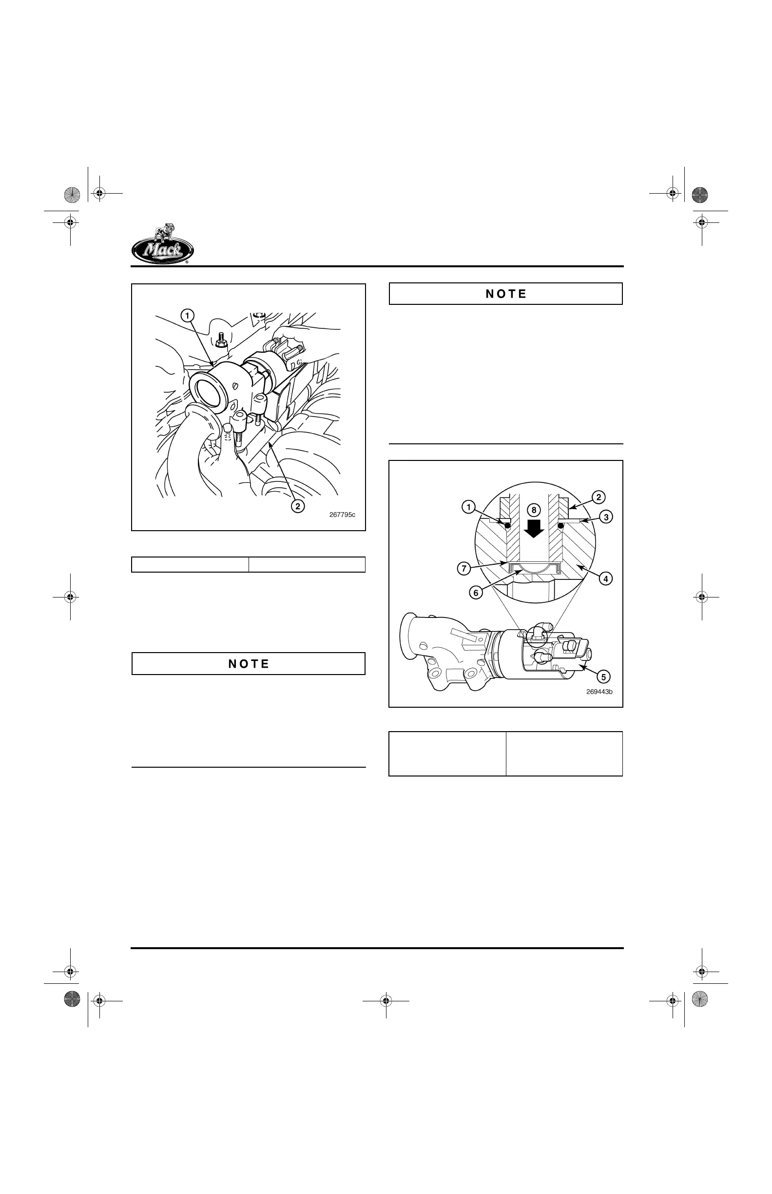
Beginning with March 2004 production, a filter
screen has been added to the oil inlet port on the
EGR valve. It is retained in place by a wave
washer and inlet hose fitting (Figure 504). Valves
fitted with the filter screen are identified by a
green dot (interim identification) on the valve
body or by the new part number, 691GC514C, on
the sheet metal cover. When connecting the oil
line to the EGR valve, make sure that the screen
and wave washer are in place and secured by the
hose fitting.
504
Figure 504 — EGR Valve Oil Inlet Filter Screen
10. Connect the electrical lead to the terminal on
the valve assembly.
1. EGR Valve Assembly 2. Exhaust Manifold
1. O-Ring
2. Fitting Jam Nut
3. Integral Washer
4. Valve Body
5. Part Number Location
6. Filter Screen
7. Wave Washer
8. Oil Flow Direction
5-111.bk Page 414 Monday, July 10, 2006 2:26 PM