REPAIR INSTRUCTIONS, PART 2
Page 423
REMOVAL AND INSTALLATION PROCEDURE
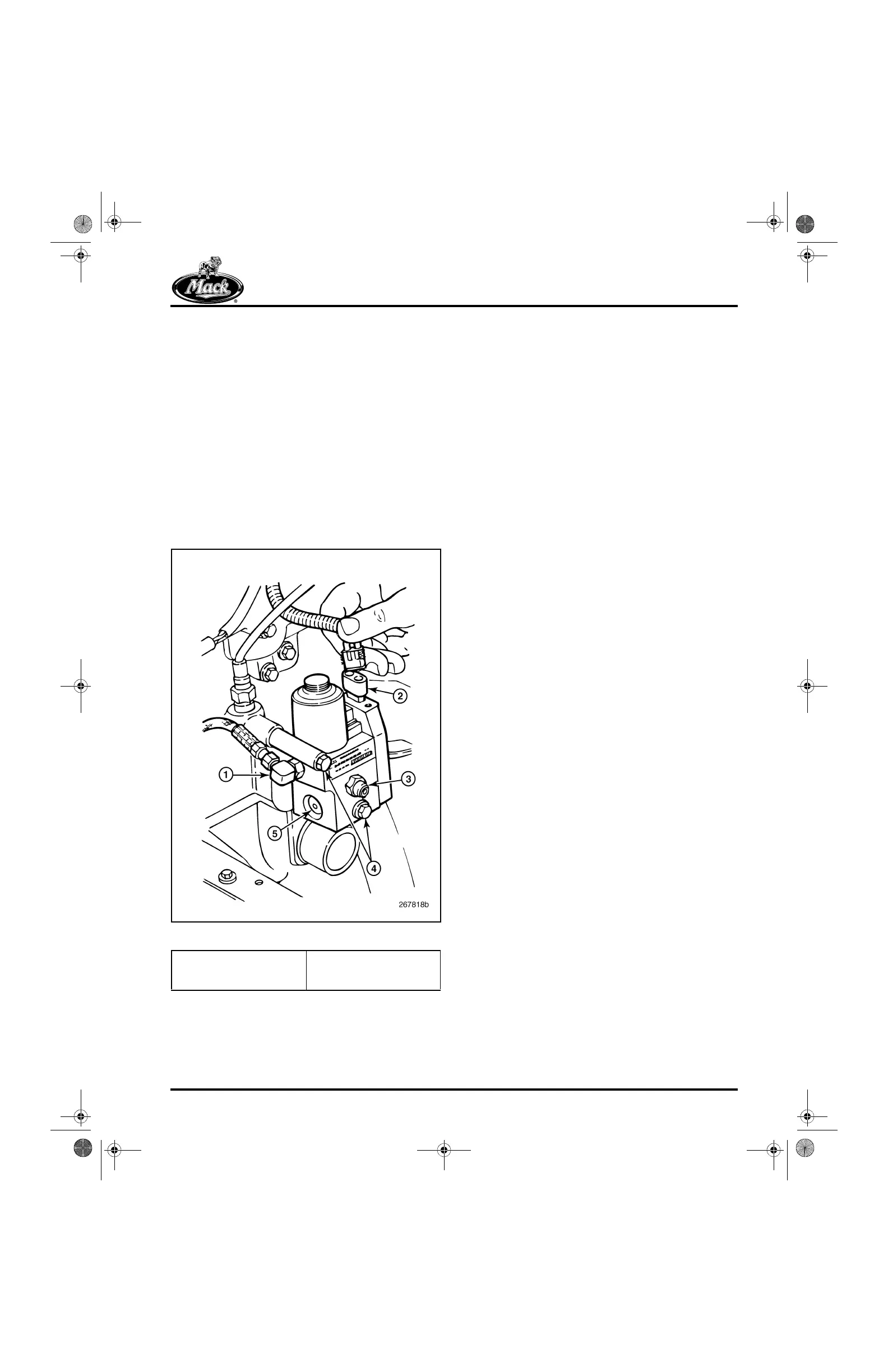
Refer to Figure 513 for reference in removing and
installing the VTG position control valve.
1. Disconnect the harness electrical lead from
the terminal on the control valve assembly.
2. Disconnect the VTG position actuator air
supply line from the valve.
3. Disconnect the air line from the air supply
port on the valve.
4. Loosen and remove the two capscrews
attaching the valve to the inlet manifold.
5. Check the valve for proper operation.
Replace as required.
513
Figure 513 — VTG Position Control Valve
6. Place the control valve assembly in position
on the inlet manifold and install the two
mounting capscrews. Tighten the capscrews
to specification.
7. Connect the air supply line to the air supply
port on the valve.
8. Connect the actuator air line to the fitting at
the side of the valve.
9. Connect the harness electrical lead to the
terminal at the top of the valve.
1. Air Line to Turbocharger
2. Electrical Connector
3. Air Supply Port
4. Mounting Capscrews
5. Air Bleed Port
5-111.bk Page 423 Monday, July 10, 2006 2:26 PM