Page 440
REPAIR INSTRUCTIONS, PART 2
Complete diagnostic procedures for wheel speed
sensor faults are outlined in the V-MAC
®
III
Service Manual, 8-311. When diagnostic
procedures indicate that the turbocharger wheel
speed sensor must be replaced, replacement
procedures are as follows:
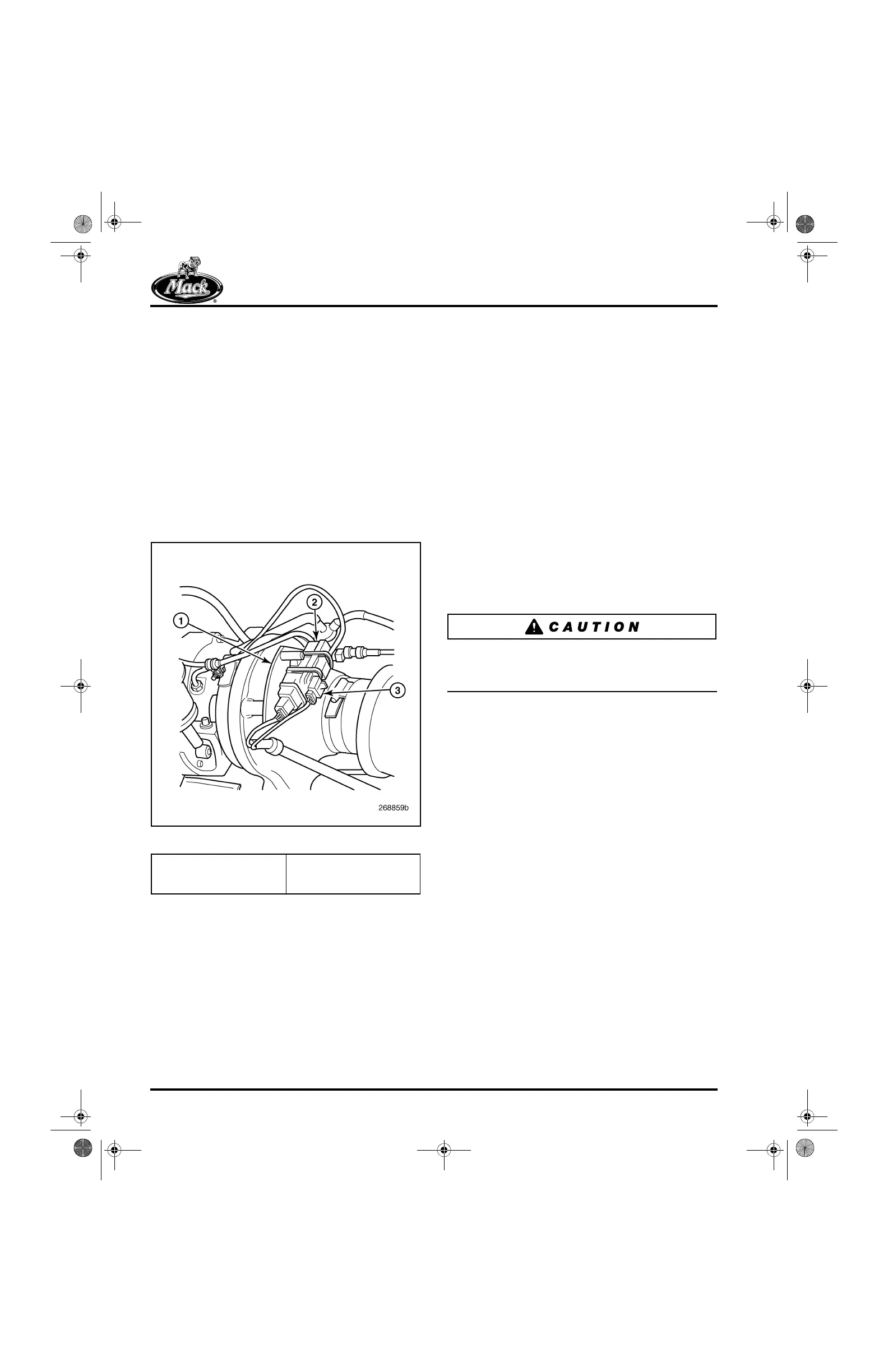
1. Cut the two tie straps that attach the
turbocharger wheel speed sensor harness
connector to the front of the vane position
sensor module at the front of the
turbocharger compressor housing
(Figure 538). Note the way the position
sensor and wheel speed sensor wires are
routed, and also note the orientation of the
harness clamp.
538
Figure 538 — Wheel Speed Sensor Connector
2. Disconnect the sensor harness connector.
The connector is located at the front of the
actuator position sensor that is mounted on
the front of the turbocharger compressor
housing.
3. Loosen and remove the nut and washer that
secures the wire harness clamp to the
turbocharger compressor housing V-band
clamp, then remove the clamp.
4. Using a 13 mm wrench, remove the sensor
from the turbocharger bearing housing.
Installation of the replacement sensor is the
reverse of removal. Tighten the sensor to
106 lb-in (12 N폷m). Route the wire harness in
such a way so as to prevent contact with any hot
surfaces of the turbocharger. Tighten the clamp
retaining nut to 48 lb-in (5.4 N폷m), and use two tie
straps to attach the wire harness connectors to
the front of the vane position sensor module.
Incorrect position sensor and wheel speed sensor
wire harness routing can result in damage to the
harnesses.
1. Thermal Isolation Plate
2. Vane Position Sensor
Module
3. Wheel Speed Sensor
Harness Connector
5-111.bk Page 440 Monday, July 10, 2006 2:26 PM