Page 454
REPAIR INSTRUCTIONS, PART 3
Continuation of Adjustments for Remaining
Cylinders
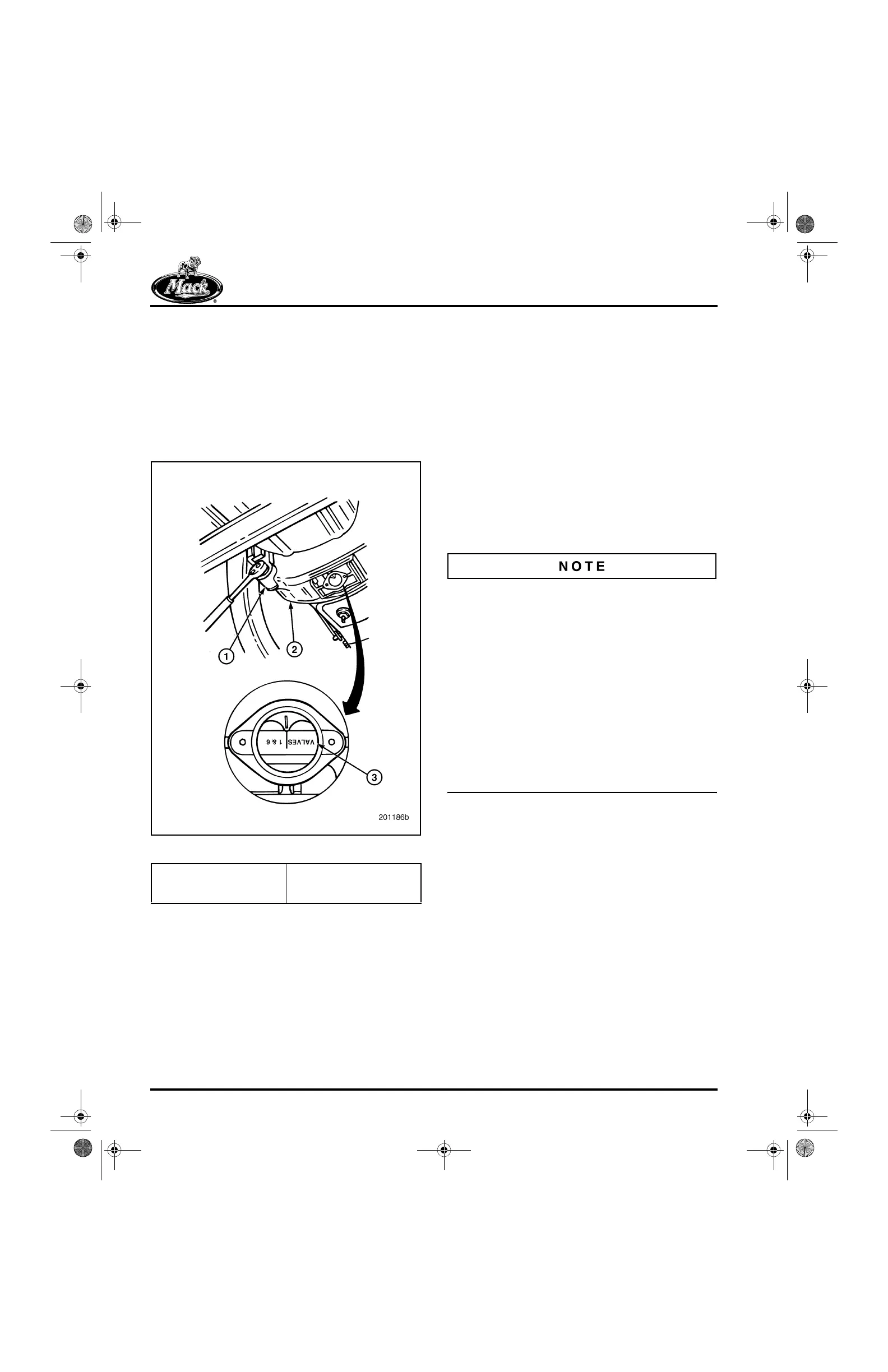
1. Using a barring socket, manually rotate the
engine crankshaft (Figure 560) in normal
rotation direction 120 degrees until the
center of the timing pointer hole in the
flywheel housing aligns with the “2 and 5”
mark on the flywheel and the No. 5 piston is
on the compression stroke.
560
Figure 560 — Valve Adjustment Markings on Flywheel
2. Adjust the final intake and exhaust valve
lash, and engine brake slave piston lash for
cylinder No. 5 as described for cylinder
No. 1. Continue this procedure for each of
the remaining cylinders, following the engine
firing order sequence, 1-5-3-6-2-4.
VALVE YOKE, BRAKE LASH AND VALVE
LASH ADJUSTMENT FOR ENGINES
EQUIPPED WITH MACK POWERLEASH™
ENGINE BRAKE
Valve adjustments are made in firing order
sequence (1-5-3-6-2-4) with the engine cold
(coolant temperature below 100°F [38°C]), not
running and with the piston at 30 degrees after
top dead center on the compression stroke (inlet
valve closed). The flywheel is marked in
120-degree increments to indicate markings on
the flywheel by removing the cover from the
bottom of the flywheel housing. Tool J 38587-A,
which engages the flywheel through the access
hole in the flywheel housing, is recommended to
rotate the engine.
Engines equipped with PowerLeash™ brake
have TWO ADJUSTING SCREWS located on
each exhaust rocker arm and a different
procedure. The rocker arm adjusting screw at the
push rod was traditionally used for adjusting
valve lash. With PowerLeash™, this adjusting
screw is used for BRAKE LASH ADJUSTMENT.
A second adjusting screw, located at the other
end of the rocker arm just above the valve yoke is
used for VALVE LASH ADJUSTMENT. The push
rod must be fully compressed and the brake lash
adjustment set first, and then with the push rod
remaining fully compressed and the brake lash
feeler gauge remaining in-place, the exhaust
valve lash adjustment is performed.
Adjust the valve yokes at the exhaust valve
positions using the following procedure. As these
engines are equipped with the self-leveling
pinless valve yokes at the inlet positions, only the
exhaust valve yokes need to be adjusted. Valve
yoke balance, engine brake lash and valve lash
must be adjusted in the following order:
a. Valve yoke balance is adjusted first.
b. Engine brake actuator lash is adjusted
second, using the adjusting screw on
the push rod side of the rocker arm.
c. Valve lash is adjusted last, using the
adjusting screw located over the valve
yoke.
1. Barring Socket
J 38587-A
2. Flywheel Housing
3. Flywheel
5-111.bk Page 454 Monday, July 10, 2006 2:26 PM
 Loading...

