Page 456
REPAIR INSTRUCTIONS, PART 3
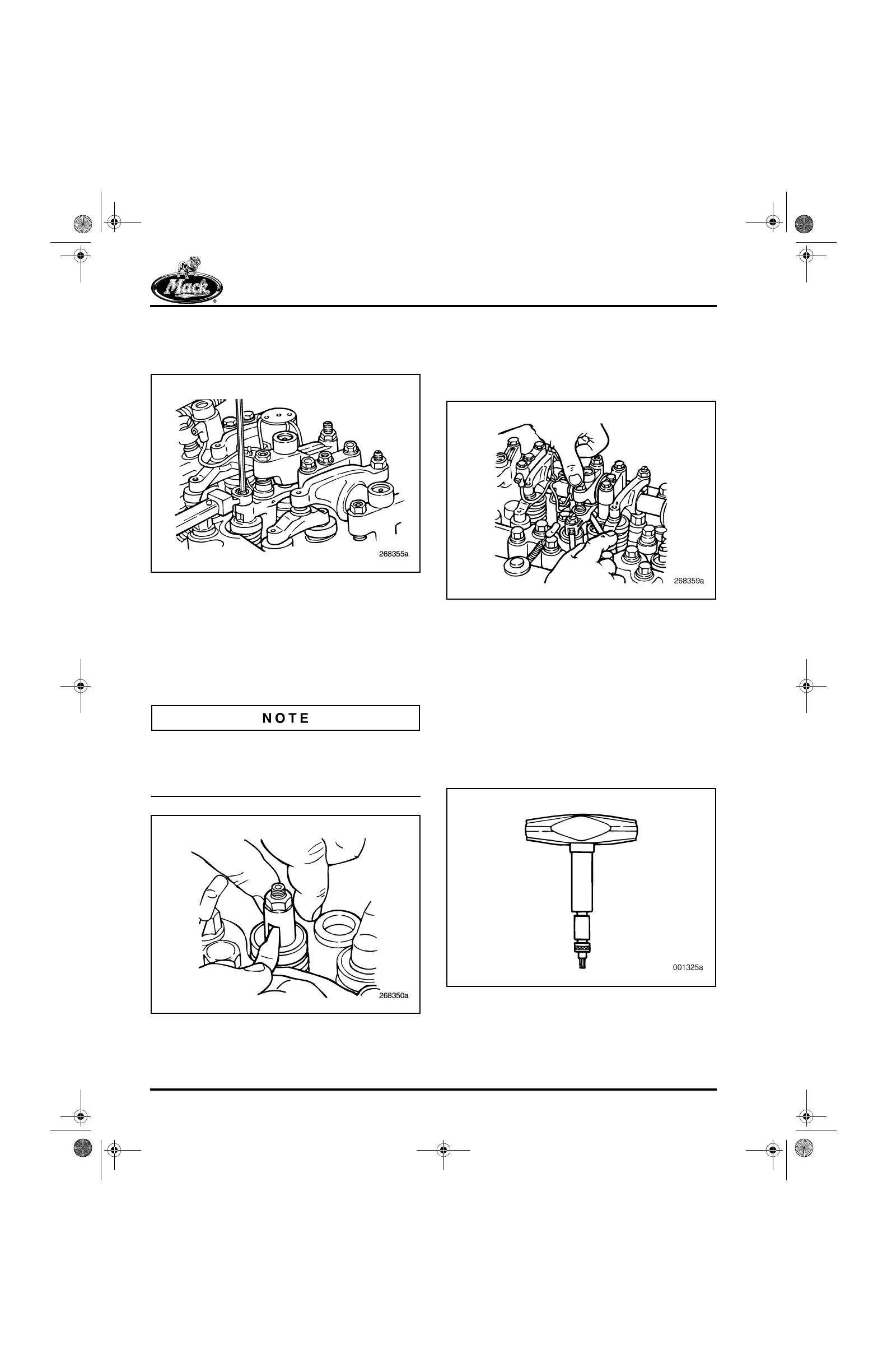
5. While holding the valve yoke adjusting
screw in this position, tighten the adjusting
screw locknut to 33 lb-ft (44 N폷m).
565
Figure 565 — Tightening Valve Yoke Locknut
6. Check the valve yoke adjustment by
inserting 0.010-inch (0.25 mm) thickness
gauges between the inboard and outboard
valve stem tips and the valve yoke. It will be
necessary to pull the valve yoke up to insert
the thickness gauge between the valve stem
tip and the yoke.
Inserting the thickness gauges may be made
easier if the gauge is inserted under the inboard
portion of the valve yoke first, then under the
outboard portion.
566
Figure 566 — Inserting Thickness Gauge
7. While exerting a moderate force on the
rocker arm end above the yoke, check that
an equal “drag” is felt on both thickness
gauges. If drag is not equal, readjust the
valve yoke.
567
Figure 567 — Checking Valve Yoke Adjustment
Brake Actuator Lash Adjustment
(PowerLeash™ Brake Engines)
Spring-loaded push rods are used at the exhaust
valve locations. In order to properly adjust the
engine brake hydraulic actuator lash, the push
rod springs must be compressed. In addition to
the hand tools normally used to adjust valves, a
T-handle torque screwdriver (tool No. J 29919)
with a 5 mm internal hex bit is required. This
torque screwdriver is preset to 6 lb-in.
568
Figure 568 — T-Handle Torque Screwdriver, J 29919
5-111.bk Page 456 Monday, July 10, 2006 2:26 PM
 Loading...

