Page 476
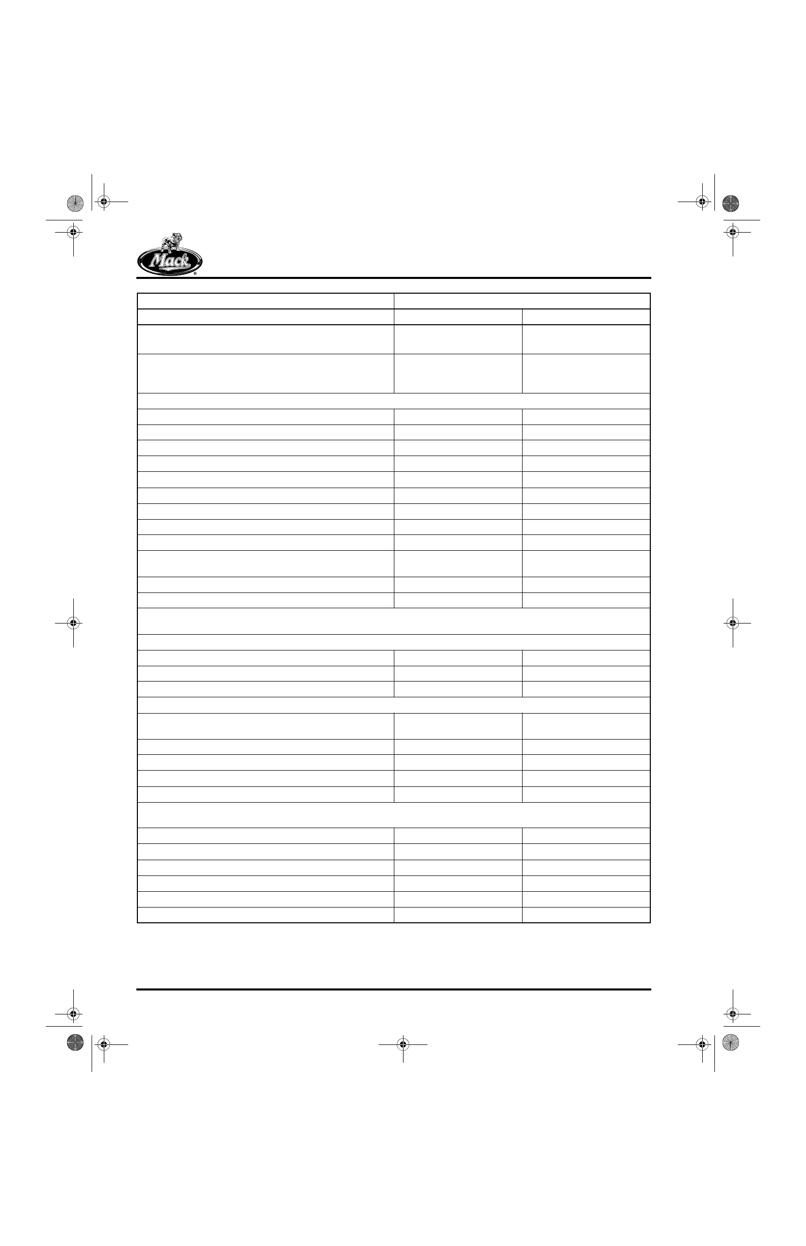
SPECIFICATIONS
Push Rod Overall Length (intake)
(from ball end, 0.560 in./14.224 mm ball placed in cup)
14.108–14.170 in. 358.343–359.918 mm
Push Rod Overall Length (spring-loaded exhaust
[compressed])
(from ball end, 0.0560 in./14.224 mm ball placed in cup)
14.086–14.148 in. 357.784–359.359 mm
TIMING GEAR AND FRONT COVER
Idler Gear-to-Camshaft Gear Backlash 0.001–0.008 in. 0.025–0.203 mm
Camshaft Gear-to-Auxiliary Shaft Gear Backlash 0.001–0.009 in. 0.025–0.229 mm
Camshaft Gear-to-Fuel Supply Pump Gear Backlash 0.001–0.019 in. 0.025–0.483 mm
Crankshaft Gear-to-Idler Gear Backlash 0.001–0.008 in. 0.025–0.203 mm
Dowel Pin Hole (round pin, in front cover, RH) 0.5005–0.5012 in. 12.7127–12.7305 mm
Dowel Pin Hole (blade pin, in front cover, LH) 0.5577–0.5584 in. 14.1656–14.1834 mm
Dowel Pin OD (round pin, RH) 0.5000–0.5004 in. 12.7000–12.7102 mm
Dowel Pin OD (blade pin, LH) 0.5571–0.5575 in. 14.1504–14.1605 mm
Crankshaft Seal Mounting Bore 3.9995–4.0025 in. 101.5873–101.6635 mm
Timing Gear Cover Seal Mounting Bore-to-Crankshaft
Runout
0.015 in. TIR (Max) 0.381 mm TIR (Max)
Timing Gear Cover Seal Square-to-Crankshaft 0.010 in. (Max) 0.254 mm (Max)
Hydraulic Steering Pump Mounting Bore 3.2525–3.2545 in. 82.6135–82.6643 mm
Note: Must be held relative to main bearing bores. Check runout with an alignment bar installed through the cylinder block
main bearing bores.
TURBOCHARGER
Shaft End Play (models S300, S400, S410) 0.002–0.005 in. 0.051–0.127 mm
Radial Tilt (measured at shaft ends) 0.046 in. (MAX) 1.168 mm (MAX)
Bearing Radial Check (measured at compressor wheel nut) 0.018–0.029 in. 0.4572–0.7366 mm
VALVES
Lash Setting, Rocker Arm-to-Valve Guide Yoke Clearance
(cold*):
Inlet (adjustment at scheduled intervals) 0.016 in. 0.406 mm
Inlet (acceptable range for interim checks) 0.012–0.020 in. 0.305–0.508 mm
Exhaust (adjustment at scheduled intervals) 0.024 in. 0.601 mm
Exhaust (acceptable range for interim checks) 0.020–0.028 in. 0.508–0.711 mm
* Note: Valve Yoke Setting must be completed at each location with the respective piston at TDC firing position prior to
setting the (cold static) rocker arm lash. (See procedure for engines with J-Tech™ or MACK PowerLeash™ engine brakes.)
Valve Face-to-Deck (inlet) 0.047 + 0.009/−0.007 in. 1.194 + 0.229/0.178 mm
Valve Face-to-Deck (exhaust) −0.021 + 0.009/−0.007 in. −1.5334 + 0.229/0.178 mm
Valve Stem-to-Guide (inlet) 0.0015–0.0035 in. 0.0381–0.0889 mm
Valve Stem-to-Guide (exhaust) 0.0025–0.0045 in. 0.0635–0.1143 mm
Valve Stem OD (inlet, 3/8 in.) 0.373–0.372 in. 9.474–9.449 mm
Valve Stem OD (exhaust, 3/8 in.) 0.3720–0.3710 in. 9.4488–9.4234 mm
Tolerances Are Shown Low to High Standard Size or Fit
Component English Metric
5-111.bk Page 476 Monday, July 10, 2006 2:26 PM