SPECIFICATIONS
Page 489
578
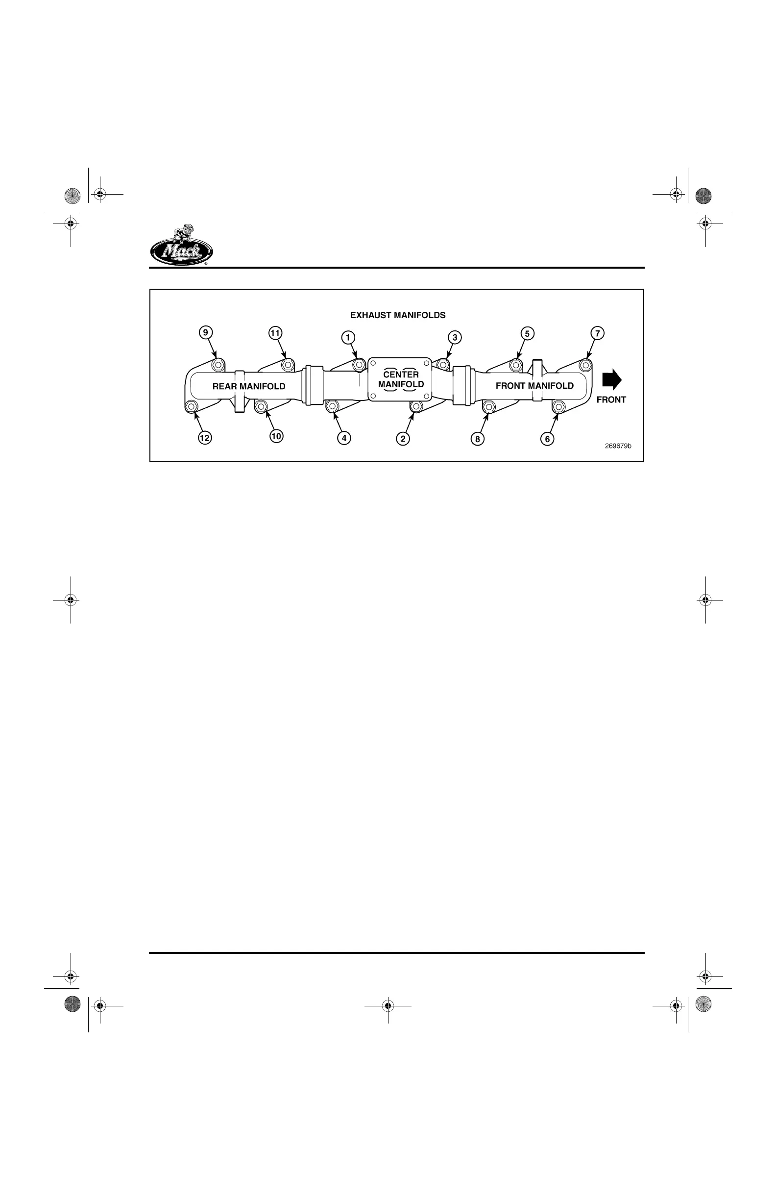
Figure 578 — Exhaust Manifold Tightening Sequence
NOTE 5 — VALVE YOKE SETTING
1. Push down on the slipper face of the yoke.
Turn down the yoke adjusting screw until it
contacts the outboard valve stem tip, as
sensed by a light drag on the adjusting
screw.
2. Turn the adjusting screw an additional
60 degrees (1/6 turn) clockwise.
3. Holding the yoke adjusting screw in this
position, lock the jam nut.
NOTE 6 — HOSE CLAMP INSTALLATION
POSITIONING INFORMATION
The band of any hose clamp in all installations
should be a minimum of 0.090 inch (2.3 mm) from
the end of the hose and must be clear of the tube
bead.
NOTE 7 — PIPE PLUG SEALING
All pipe plugs must be sealed using Loctite
®
PST
pipe thread sealant with Teflon
®
, or equivalent.
NOTE 8 — CYLINDER SLEEVE ID
Cylinder sleeve ID may be 4.872 inches
(123.749 mm) minimum at the top of the sleeve
due to close-in from the press fit.
NOTE 9 — REAR SEAL BORE RADIAL
RUNOUT
Runout is to be checked with an alignment bar
installed through the cylinder block main bearing
bores.
5-111.bk Page 489 Monday, July 10, 2006 2:26 PM