Page 44
DESCRIPTION AND OPERATION
41
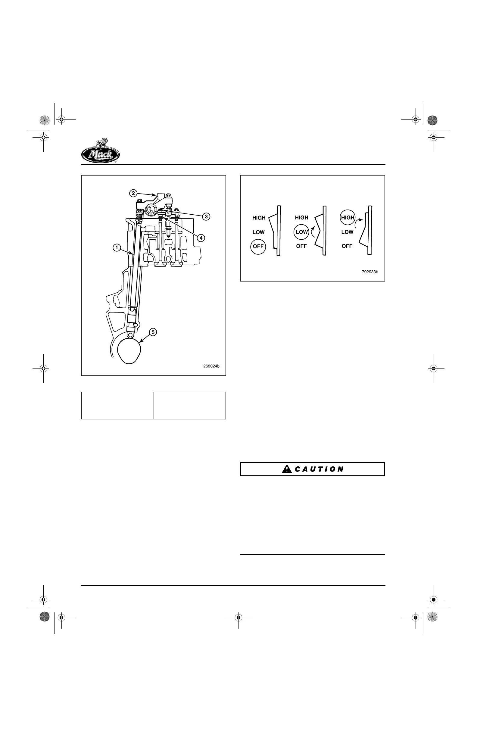
Figure 41 — MACK Engine Brake Cut-Away View
Use of the MACK PowerLeash™ engine brake is
controlled by a dash-mounted switch that has two
power positions: a LOW position to apply
approximately one-half (three cylinders) of the
engine brake retarding capability, and a HIGH
position to apply full retarding power (all six
cylinders). The choice of LOW or HIGH operation
depends on the driving situation, vehicle load and
downhill percent grade. When the switch is in the
OFF position, the engine brake is deactivated.
42
Figure 42 — Dash-Mounted Engine Brake Switch
Engine brake operation is controlled by the
V-MAC
®
system. A constant 12 volts at a low
current is supplied to the engine brake solenoids
at all times. When the dashboard switch is turned
ON and no fuel is requested (0% throttle), the
engine electronic control unit (EECU) increases
the current to the engine brake solenoids,
causing the solenoid coils to energize.
When the engine brake is “enabled” (switch in
either LOW or HIGH position), the V-MAC
electronic control system commands engine
brake power (engine brake “active”) only when
the following conditions are true:
앫 The foot-operated engine accelerator pedal
is not depressed.
앫 The clutch pedal is not depressed (manual
shift transmissions only).
앫 The engine speed is at least 900 rpm.
앫 Coolant temperature is above 125°F (52°C).
Engine stalling and potential engine damage can
occur if the engine brake is operated at cold
engine oil temperatures. The V-MAC engine
control system includes a feature that prevents
the engine brake from being activated until the
engine coolant temperature reaches at least
125
°
F (52
°
C). The engine brake will not function
until sufficient engine warm-up time has elapsed,
regardless of the dashboard engine brake switch
setting.
1. Spring-Loaded Push Rod
2. Engine Brake Hydraulic
Actuator
3. Valve Actuating Pin
4. Valve Stem Tip Cap
5. Camshaft with Engine
Brake Profile
5-111.bk Page 44 Monday, July 10, 2006 2:26 PM