DESCRIPTION AND OPERATION
Page 75
87
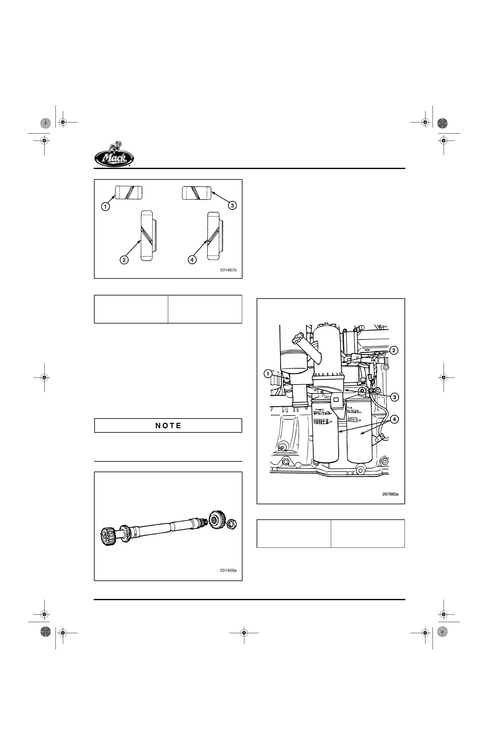
Figure 87 — Oil Pump Drive Gears
The ASET™ oil pump also differs from the E7 oil
pump in that it is designed to accommodate the
faster auxiliary shaft speed. In addition, the
auxiliary shaft used on the ASET™ engines
(Figure 88) is through-drilled to carry oil to the
rear auxiliary shaft bushing. This is different from
the E7 engine, which provides oil to the rear
bushing through a cylinder block oil passage. An
E7 shaft CANNOT be used in an ASET™ engine.
Doing so will result in failure of the auxiliary shaft
rear bushing and the air compressor.
The ASET™ auxiliary shaft is identified by three
machined circumferential cuts in front of the
stamped part number.
88
Figure 88 — Auxiliary Shaft
OIL COOLER AND FILTER MOUNTING
BRACKET
The engines are equipped with a plate-type oil
cooler and a centrifugal oil filter assembly, called
Centri-Max
®
ULTRA or ULTRA PLUS, that is
inverted and mounted on top of the bracket. With
this arrangement, the filter housing includes the
oil fill port.
The main member to which the oil cooler and oil
filters are mounted is a one-piece aluminum
casting which bolts to the four-bolt pad on the
cylinder block. An oil drain passage within the
casting allows the oil from the centrifugal filter to
drain back to the crankcase.
89
Figure 89 — Oil Cooler/Filter Mounting Bracket
1. E7 Oil Pump Gear (12
Teeth)
2. E7 Aux. Pump Gear (18
Teeth)
3. ASET™ Oil Pump Gear
(13 Teeth)
4. ASET™ Aux. Shaft Gear
(17 Teeth)
1. Oil Cooler
2. Centri-Max
®
ULTRA or
ULTRA PLUS Oil Filter
3. Oil Filter Mounting
Bracket
4. Spin-On, Full-Flow Oil
Filters
5-111.bk Page 75 Monday, July 10, 2006 2:26 PM