Manitowoc Published 08-12-19, Control # 224-13_v2 4-103
MLC650 OPERATOR MANUAL SET-UP AND INSTALLATION
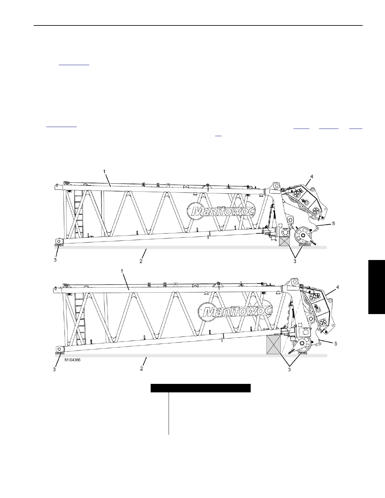
Assemble Top to Boom Inserts
The boom top can be shipped in either of the configurations
shown in Figure 4-80
:
• Configuration A: the lower boom points are unpinned
from the working position in the boom top. This
configuration provides the lowest shipping height.
• Configuration B: the lower boom points are pinned to the
working position in the boom top. This configuration can
be used if there are no shipping height restrictions.
See Figure 4-79
, for the following steps.
1. Lift the boom top (10) off the trailer in the same manner
the inserts were removed from the trailers.
If the boom top is in Shipping Configuration A, the lower
boom points (and wire rope guide) will rotate down to the
working position against the boom top bearing plates as
the boom top is lifted.
2. Lift the boom top into position and engage the fixed
horizontal pins (13) with the hooked connectors (14) on
the insert.
3. Lower the boom top until the bottom connector holes are
aligned.
4. Install the bottom pins (15) in the same manner the
inserts were connected. See step 9
or step 10 on page
97.
5. Block under the boom top as needed.
6. Disconnect the lifting slings.
FIGURE 4-80
Item Description
1Boom Top
2Trailer
3 Blocking
4 Wire Rope Guide
5 Lower Boom Points (1, 2, or 3)
Shipping Configuration A
Shipping Configuration B