6C-32 90-13645--2 495POWER-TRIM
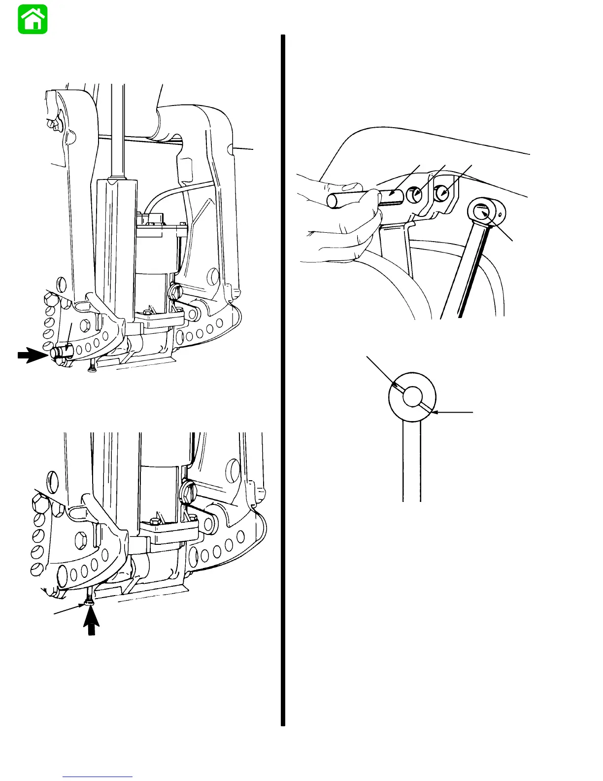
4. Using a suitable punch, drive lower pivot pin into
clamp bracket and trim cylinder assembly until
pivot pin is flush with outside surface.
51515
a
a - Lower Pivot Pin
5. Using a suitable punch, drive lower cross pin into
its respective bore until seated.
51515
a
a - Lower Cross Pin
6. Apply 2-4-C w/Teflon (92-825407A12) to surface
of upper pivot pin, pivot pin bore and trim ram
bore.
NOTE:
Install trim ram with cross hole located as
shown .If trim ram is installed reversed, the trim send-
er (if installed) will not operate.
51515
Transom Side
Cross Hole
Engine Side
d
c
bab
a - Pivot Pin
b - Pivot Pin Bore
c - Trim Ram Bore
d - Install Trim Ram As Shown