3A-8 90-13645--2 495FUEL SYSTEM AND CARBURETION
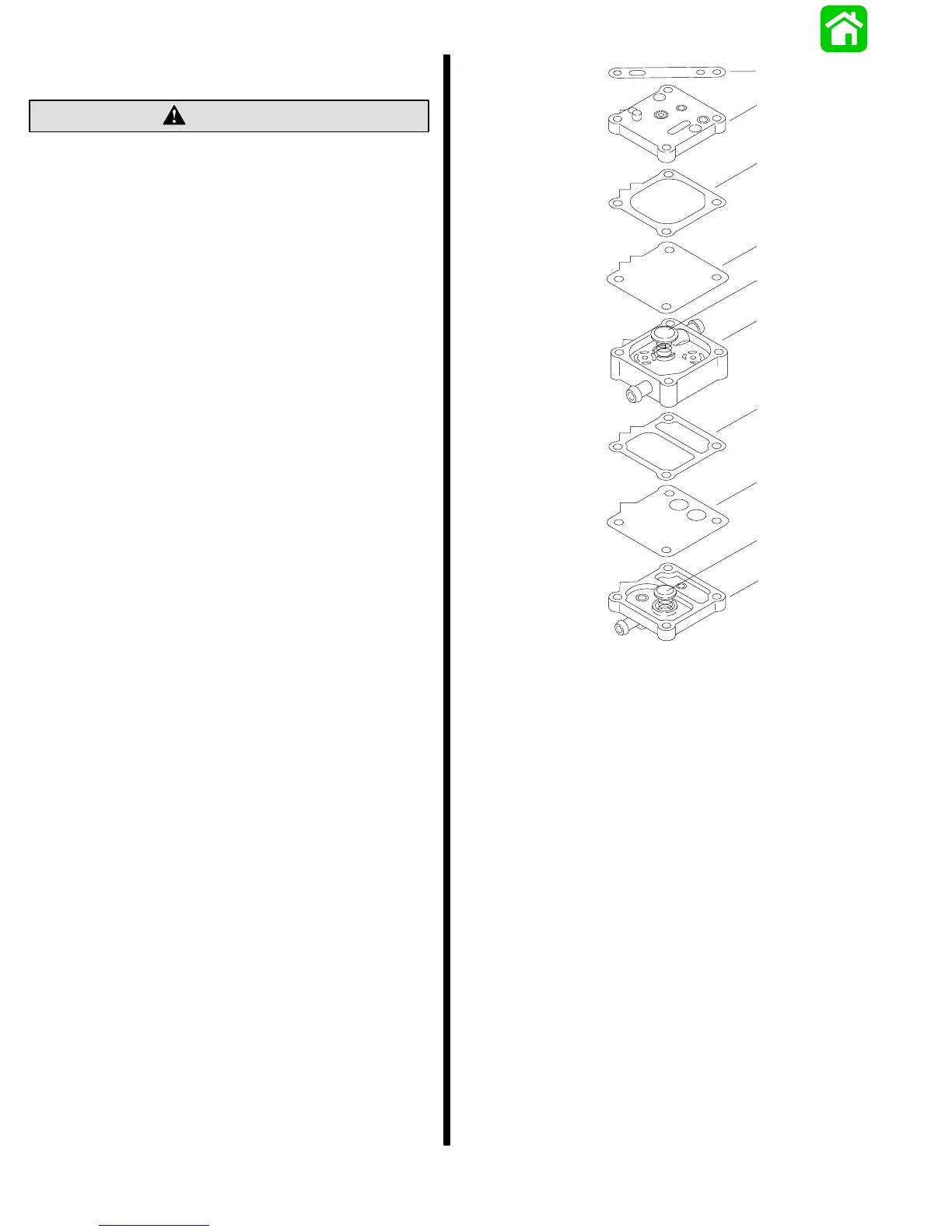
REASSEMBLY SEQUENCE (DESIGN 1)
Observe position of both Pulse Chamber
DIAPHRAGM and GASKET. The two larger holes
allow oil injection output to enter the gas flow.
Failure to reinstall as shown WILL result in
extensive damage to engine.
CAUTION
51119
a
b
c
d
e
f
g
h
i
j
a - Chamber Plate (Step 1)
b - Boost Compression Spring & Cap (Step 2)
c - Boost Chamber Gasket (Step 3)
d - Boost Diaphragm (Step 4)
e - Fuel Pump Body (Step 5)
f - Main Compression Spring & Cap (Step 6)
g - Fuel Pump Diaphragm (Step 7)
h - Pulse Chamber Gasket (Step 8)
i - Fuel Pump Base (Step 9)
j - Fuel Pump to Powerhead Gasket - Shown for
Identification Purposes Only
Reinstalling Fuel Pump to Powerhead -
see preceding page