Spitfire – Maintenance Manual
60
AP-74096, Rev. 1.0, 09/06/05
Notes :
¾ Make sure the plate is cleaned properly. Dust, glue and other parts must be
removed.
Step 8 : Stick the dryer strip(s) onto the plate.
Notes :
¾ Make sure that the strips connect properly.
¾ Please make sure that the sensor (blue blocks) are positioned on the flat surface of
the front paper guide.
¾ Stick it as close as possible to the assembly holes. Make sure it does not touch the
assembly holes.
Notes :
¾ Please make sure that there are no air bubbles under the heater strip. Air bubbles
below the heater strip could cause overheating of the heater strip.
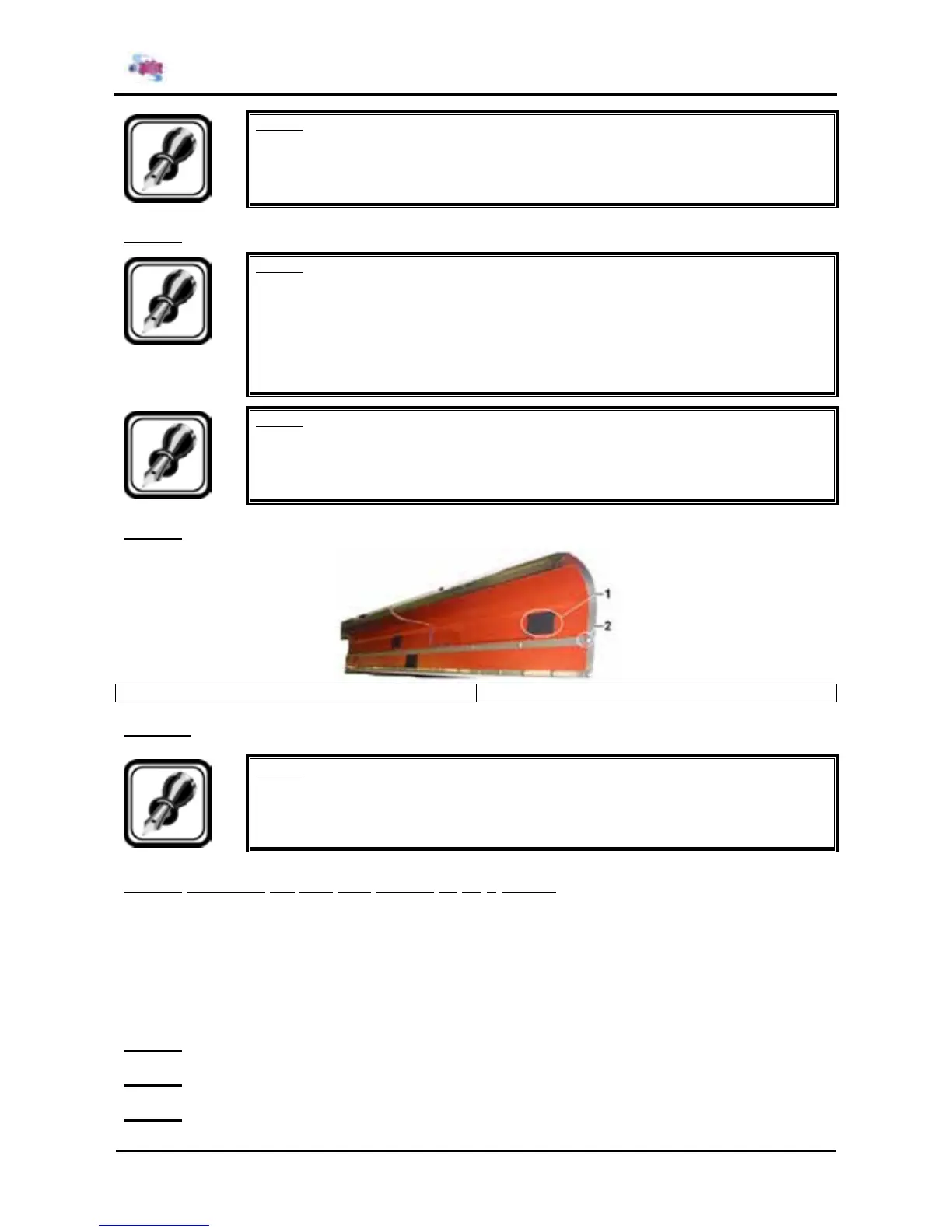
Step 9 : Stick onto the sensors a sensor insul. patch.
1 = sensor insul. patch 2 = assembly hole
Step 10 : Reinstall all parts in the opposite order of the removal procedure.
Notes :
¾ During reinstallation of the plate, make sure there are no cables stuck.
4.3.1.2. Replacing the post fixer (Heater C) on a Spitfire
Before replacing the heater, make sure to have following items:
¾ 65” model : Post Fixer C 64
¾ 90” model : Post Fixer C 87
¾ 1 x sensor insul. Patch
To replace the post fixer on a Spitfire, please follow the instructions mentioned below.
Step 1 : Remove side cover L.
Step 2 : Remove side cover R.
Step 3 : Remove the front cover.