530 7 ELECTRONIC CONTROL SYSTEMS DIAGNOSTICS
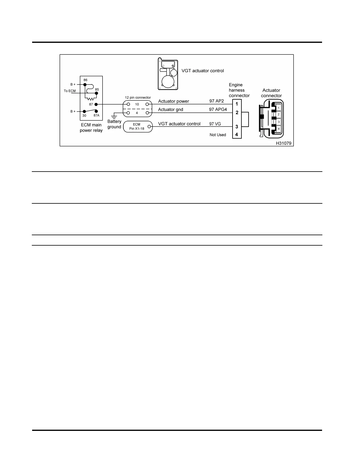
Figure 501 VGT circuit diagram
NOTE: Turn the ignition switch to OFF before disconnecting engine wiring harness connectors from
components.
See truck Ch assis Electrical Circu it D iag ram Manual for circuit numbers, connector and fuse locations.
Output State Test - Signal Check (Actuator Control Vo ltage check has been completed. Pin 2 to ECM
Chassis Ground is to specification. Co n ne c t Turbo Breakout H arness to engine harness an d actuator
harness. Run the Low and High Output State Tests. See “Diagnostic Software Operation” in Section 3 (page
68) for procedure to do the Low and High Output State Tests.)
Test State/Point Setting/Spec Comment
Output State Test -
Low
DMM set to V -
DC
Listen and observe to verify if crank leve r of VGT actuator
moves. Toggling between the Low and High Output State Tests
can be done during this test.
3to2 0Vto0.25V
If > 0.25 V, disconnect actuator harness and connect 500 Ohm
Resistor Harness between 3 and 2. Retest Output State Test
-Low.
• If > 0.25 V the concern is with engine harness or ECM,
check for a short to B+ or V
REF
. Do the Actuator Control
Voltage Check at ECM (page 534) and Harness Resistance
Checks (page 537).
• If < 0.25 V, the concern is either high resistance in wiring or
the VGT actuator. Do Harness Resistance Checks (page
537) to confirm integrity of wiring. See Chassis Electrical
Circuit Diagram Manual.
If integrity of wiring is confirmed to be in good condition,
replace VGT actuator.
Output State Test -
High
DMM set to V -
DC
Listen and observe to verify if crank leve r of VGT actuator
moves. Toggling between the Low and High Output State Tests
can be done during this procedure.
3to2 B+±0.5V
If < B+, disconnect actuator harness and connect 500 Ohm
Resistor Harness between 3 and 2. Retest Output State Test
-High.
EGES-270-1
Read all safety instructions in the "Safety Information" section of this manual before doing any procedures.
Follow all warnings, cautions, and notes.
© August 2008 Navistar, Inc.
 Loading...


