Technical Reference Guide – Interface specifications > 25
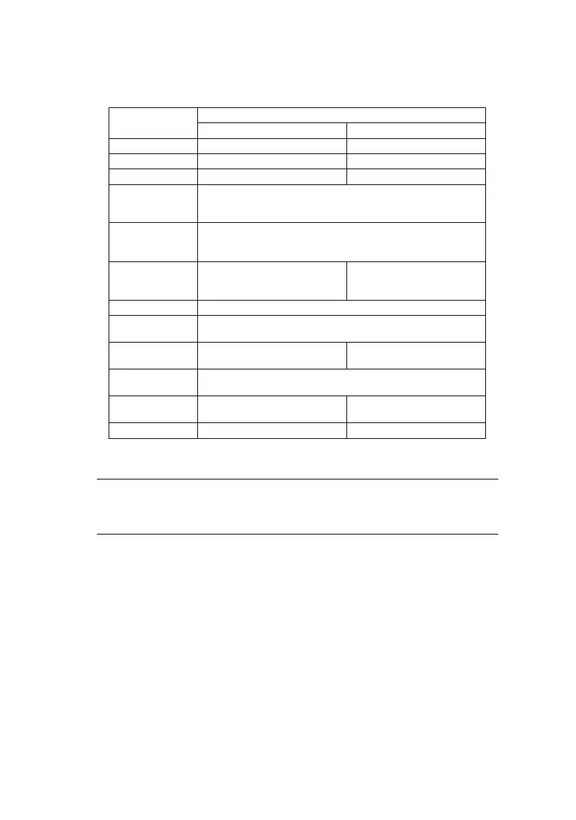
Signalling levels
NOTE
Signalling Levels
Bus State
Required Acceptable
Differential “1” (D+)-(D-)> 200mV and D+ > V
IH
(min) (D+)-(D-)> 200mV
Differential “0” (D-)-(D+)> 200mV and D- > V
IH
(min) (D-)-(D+)> 200mV
Single-ended 0 (SE0) D+ and D- < V
IL
(max) D+ and D- < V
IH
(min)
Data J state:
Low-speed
Full-speed
Differential “0”
Differential “1”
Data K state:
Low-speed
Full-speed
Differential “1”
Differential “0”
Idle state:
Low-speed
Full-speed
D- > V
IHZ
(min) and D+ < V
IL
(max)
D+ > V
IHZ
(min) and D- < V
IL
(max)
D- > V
IHZ
(min) and D+ < V
IH
(min)
D+>V
IHZ
(min) and D- < V
IH
(min)
Resume state Data K state
Start-of-
Packet (SOP)
Data lines switch from Idle to K state
End-of-Packet (EOP)
SE0 for ≥ 1 bit time
1
followed by a J
state for 1 bit time
SE0 for ≥ 1 bit time
1
followed by a J
state
Disconnect
(at downstream port)
SE0 for ≥ 2.5μs
Connect
(at downstream port)
Idle for ≥ 2ms Idle for ≥ 2.5μs
Reset D+ and D- < V
IL
(max) for ≥ 10ms D+ and D- < V
IL
(max) for ≥ 2.5μs
The width of EOP is defined in bit times relative to the device
type receiving the EOP. The bit time is approximate.
 Loading...