Technical Reference Guide – Interface specifications > 28
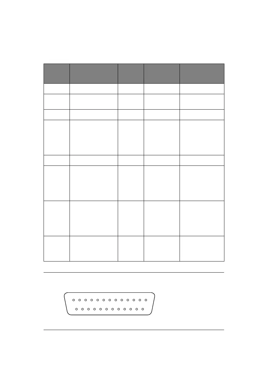
RS-232C
SERIAL
INTERFACE
SPECIFICATIONS
I
NTERFACE
SIGNALS
NOTE
PIN
NO.
SIGNAL CODE SIGNAL FUNCTION
1 Protective Ground PG — Frame ground
2 Transmitted Data TD From printer Data from
printer
3 Received Data RD To printer Data to printer
4 Request to Send RTS From printer Signal to
indicate printer
cannot receive
data in printer
Busy/Ready
protocol
7 Signal Ground SG — Signal ground
11 Supervisory Send
Data
SSD From printer Signal to
indicate printer
cannot receive
data in printer
Busy/Ready
protocol
20 Data Terminal
Ready
DTR From printer Signal to
indicate printer
cannot receive
data in printer
Busy/Ready
protocol
5, 8 to
10, 12
to 19,
21 to 25
— — — Unused
1. Connector pin arrangement for above:
(Viewed from interface cable side)
13
25
1
14