DMTA-10022-01EN, Rev. C, January 2015
List of Figures
223
List of Figures
Figure i-1 The symbols on the top of the 45MG ................................................................ 1
Figure i-2 Labels attached to the back of the instrument ................................................. 2
Figure i-3 The REGULATORY screen ............................................................................... 13
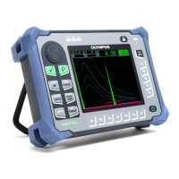
Figure i-4 The 45MG instrument ....................................................................................... 15
Figure 1-1 The 45MG hardware components — Front, top, and side views ............... 20
Figure 1-2 The 45MG connections ...................................................................................... 20
Figure 1-3 The top end connectors ..................................................................................... 21
Figure 1-4 The microSD connector behind the battery door .......................................... 21
Figure 1-5 The 45MG keypads ............................................................................................ 22
Figure 2-1 The power indicator when using batteries .................................................... 27
Figure 2-2 The power indicator when using a computer or an AC power supply ..... 28
Figure 2-3 Opening the battery compartment .................................................................. 29
Figure 2-4 Selecting the battery type ................................................................................. 31
Figure 3-1 The measurement screen — No waveform enabled ..................................... 33
Figure 3-2 The measurement screen — Waveform option enabled .............................. 34
Figure 3-3 The ID bar ........................................................................................................... 34
Figure 3-4 Other elements — No Waveform option enabled ......................................... 35
Figure 3-5 Other elements — Waveform option enabled ............................................... 36
Figure 3-6 The loss-of-signal (LOS) indicator ................................................................... 36
Figure 3-7 Menu and submenu example .......................................................................... 37
Figure 3-8 Parameter screen example ................................................................................ 38
Figure 3-9 Example of the virtual keyboard ..................................................................... 40
Figure 3-10 The character cycle of the traditional text edit method ............................... 41
Figure 4-1 The SYSTEM screen ........................................................................................... 44
Figure 4-2 The SP MENU screen ........................................................................................ 45
Figure 4-3 The CLOCK screen ............................................................................................ 45
Figure 4-4 The DISPLAY screen ......................................................................................... 46
Figure 4-5 Example of the indoor and the outdoor color schemes ............................... 47
Figure 4-6 The measurement update rate indicator ........................................................ 49
Figure 5-1 Plugging in the transducer ............................................................................... 52
 Loading...

