OMICRON 173
Off-service diagnostic methods
For the basic connection diagram, see Figure 17-5: "Principal scheme of the contact resistance test" on
page 125 and 17.2.3 "Testing circuit breakers with CIBANO 500 and the CB MC2 modules" on
page 165.
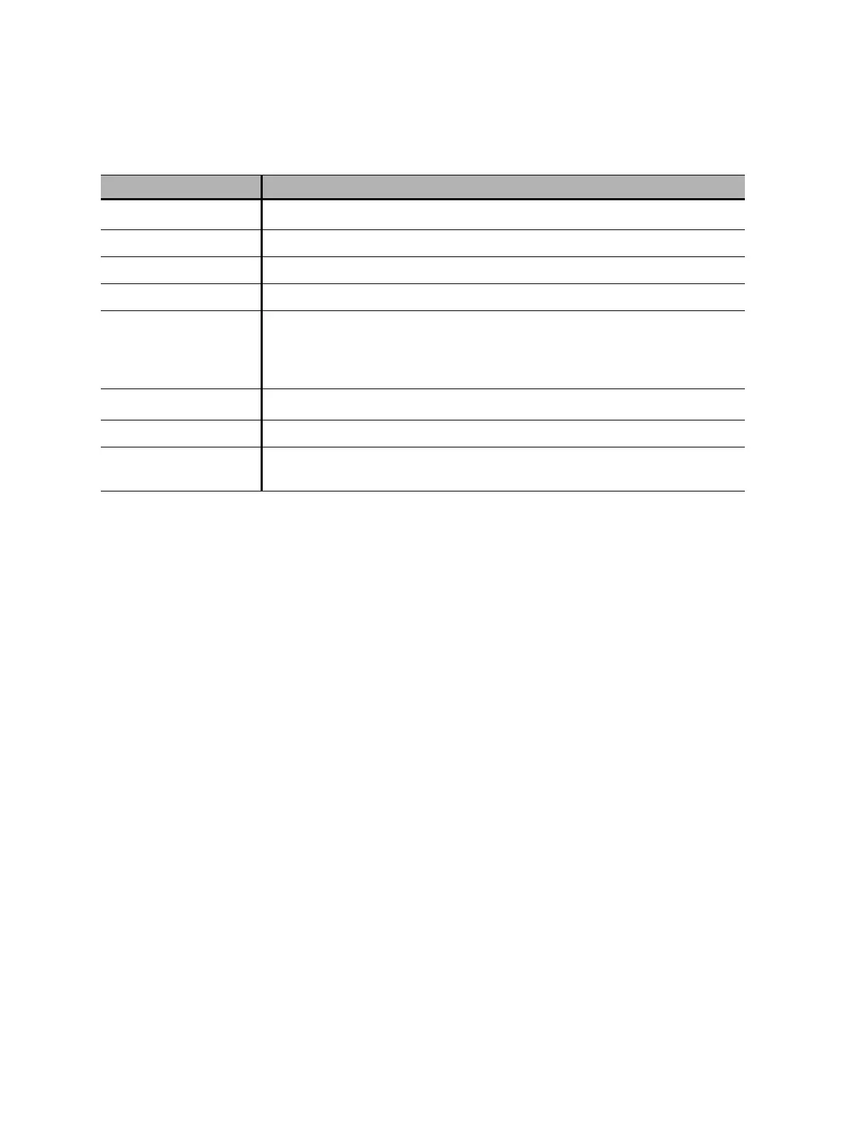
Table 17-34: Hardware configuration options of the CB MC2 module
CB MC2 Option
Module name
1
1. Permanently stored in the CB MC2 memory. You can, for example, mark your CB MC2 modules with the colored stickers and
name them according to the colors. You can also rename the CB MC2 modules depending on the connection point.
Editable name of the CB MC2 module
Phase Editable phase assignment of the CB MC2 module (stored on the device)
Channel Channel of the CB MC2 module
Active Click the socket symbol to activate or deactivate the channel.
Combine Click the Combine check box to combine the channels of the CB MC2
module. The combined CB MC2 channels can both be either active or
inactive. The measurement results are labeled with the name of channel 1,
and the voltage is only measured on channel 1.
Ch.name
1
Editable name of the CB MC2 channel
Charge Indicates the charge status of the CB MC2 module.
LED Click the LED symbol to identify the connected CB MC2 module by flashing
LED.

 Loading...


