362
Analog Output Terminals Section 7-5
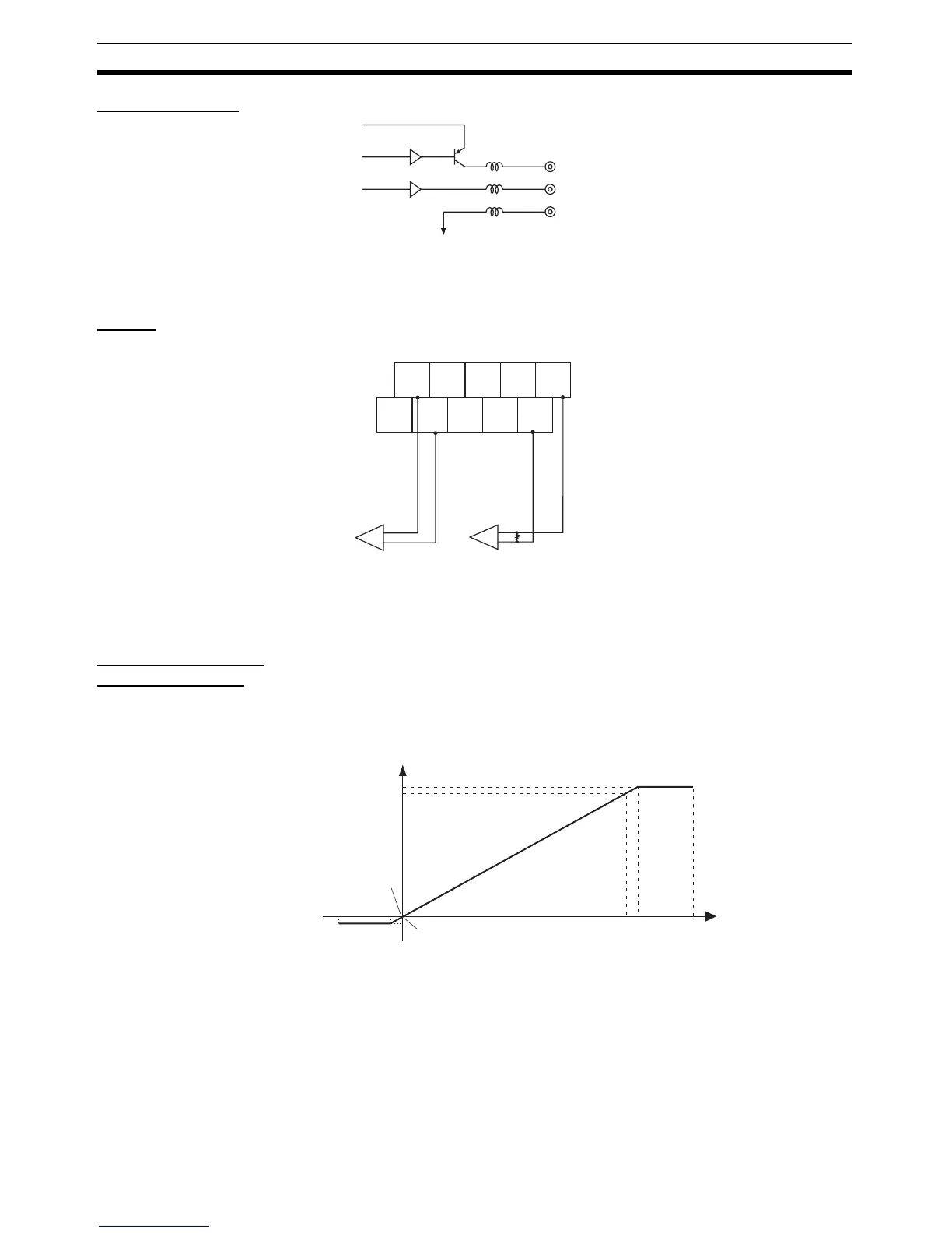
Internal Circuits
Wiring The terminal wiring varies according to whether voltage or current output is
used.
Output Range and
Conversion Data
The digital values that are output are converted to analog data according to
the output range used, as shown below. When the value exceeds the output
range, the DA conversion data is fixed at the High Limit or Low Limit set value.
Output Range: 0 to 5 V The values 0000 to 1770 hex (0 to 6,000) correspond to the voltage range 0 to
5 V. The output range is
–0.25 to 5.25 V.
V+
I+
−
Analog GND
The negative terminals for output 0
and output 1 are connected internally.
+
−
+
−
NC
I0
+
V1
+
I1
+
1
−
NC
V0
+
0
−
NC
NC
For current
output on
output 1
For voltage
output on
output 0
External
device
External
device
Note: The voltage or current output signal ranges
are set on the DIP switch or from the Configurator.
FED4 (−300)
189C
(6300)
1770
(6000)
0000 (0)
0 V
−0.25 V
5.25 V
5 V
8000
7FFF

 Loading...


