Chapter 7: Operation
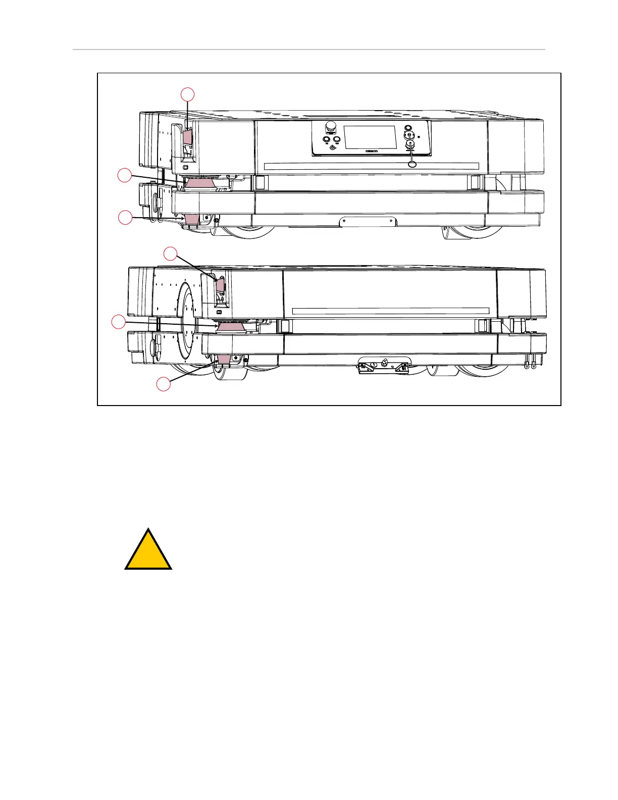
Figure 7-28. HD-1500 Lasers, (A) Low Lasers, (B) Safety Scanning Lasers, and (C) Side Lasers
Safety Scanning Lasers
Each safety scanning laser ((B) in Figure 7-28. ) provides readings in a 270° field of view, with
a typical maximum range of 30 m. With the two safety scanning lasers each covering a 270°
field of view, the HD-1500 has a full safety coverage of 360°. The lasers operate in a single
plane, positioned at 175 mm above the floor.
WARNING: PERSONALINJURYORPROPERTYDAMAGERISK
Objects protruding out, above or below the HD-1500 lasers' scanning planes
shall be configured as restricted zones during workspace map creation. This
will eliminate possible collision risk during AMR operation.
The laser cannot reliably detect glass, mirrors, and other highly-reflective objects. Use caution
when operating the platform in areas that have these types of objects. If the platform will need
to drive close to these objects, we recommend that you use a combination of markings on the
objects (e.g., tape or painted strips), and also use Forbidden Area in the map, so that the plat-
form knows to plan paths safely around these objects.
Low Lasers
The two low lasers ((A) in Figure 7-28. ) detect obstacles below the scanning plane of the safety
scanning laser, such as an empty pallet or fork truck tines, which are too low for the safety
31500-000 Rev A HD-1500 Platform User's Manual 208