247 HD-1500 Platform User's Manual 31500-000 Rev A
8.7 Replacing Non-Periodic Parts
If you order your HD-1500 with the optional side lasers, the AMR will ship with the side
lasers assembled and mounted onto the AMR. Therefore, if you decide to relocate them, you
must first remove them from the AMR.
You must determine the mounting method for the optional side lasers.
Remove the Side Laser
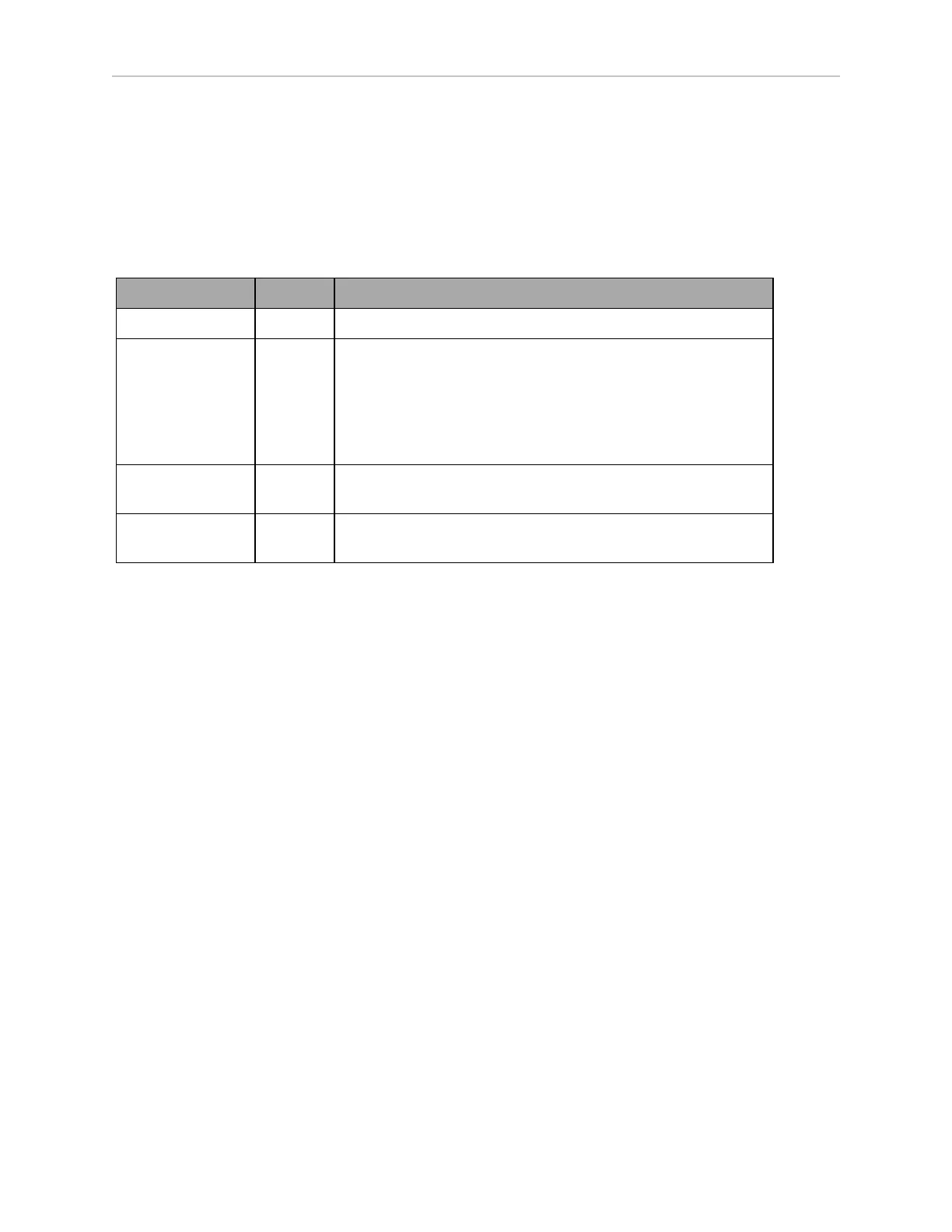
You require the following tools to remove and relocate each side laser:
Tool Qty Description
Laser TiM-510 2 Laser part number: 68220-400L.
Extension cable
kit
1 Extension cable kit options:
l
Part number: 68970-000 (includes one meter long
extension cable), or
l
Part number: 68971-000 (includes two meter long
extension cable)
Hex keys 3 2.5 mm, 3 mm, and 5 mm hex keys for M3, M4, and M6
socket head cap screws.
Loctite 243 as
needed
Loctite 243
Before you begin, press an E-Stop button and turn the HD-1500 off.
Follow these steps to remove the side laser from the AMR:
1.
Remove the front skin (for the front left side laser) or the rear skin (for the right rear side
laser) to access the back of the laser corner. See: Removing and Installing Skins on page
253
Once the skin is removed, you can access the back of the laser corner ((A) in Figure 8-39.
and remove the side laser as instructed in the following steps.
2.
Disconnect the power cable, and the data cables from the side laser.
3.
Unscrew all three M6 screws ((B) in Figure 8-39. ), and remove the laser cover fin ((C) in
Figure 8-39. ).
IMPORTANT: Care must be taken not to scratch the laser lens. The laser
lens can easily get scratched and damaged.
If you decide to install the laser cover fin back in place, you must torque the M6 screws
properly (7.5 N-m), and use Loctite 243 to secure in place.