Chapter 8: Maintenance
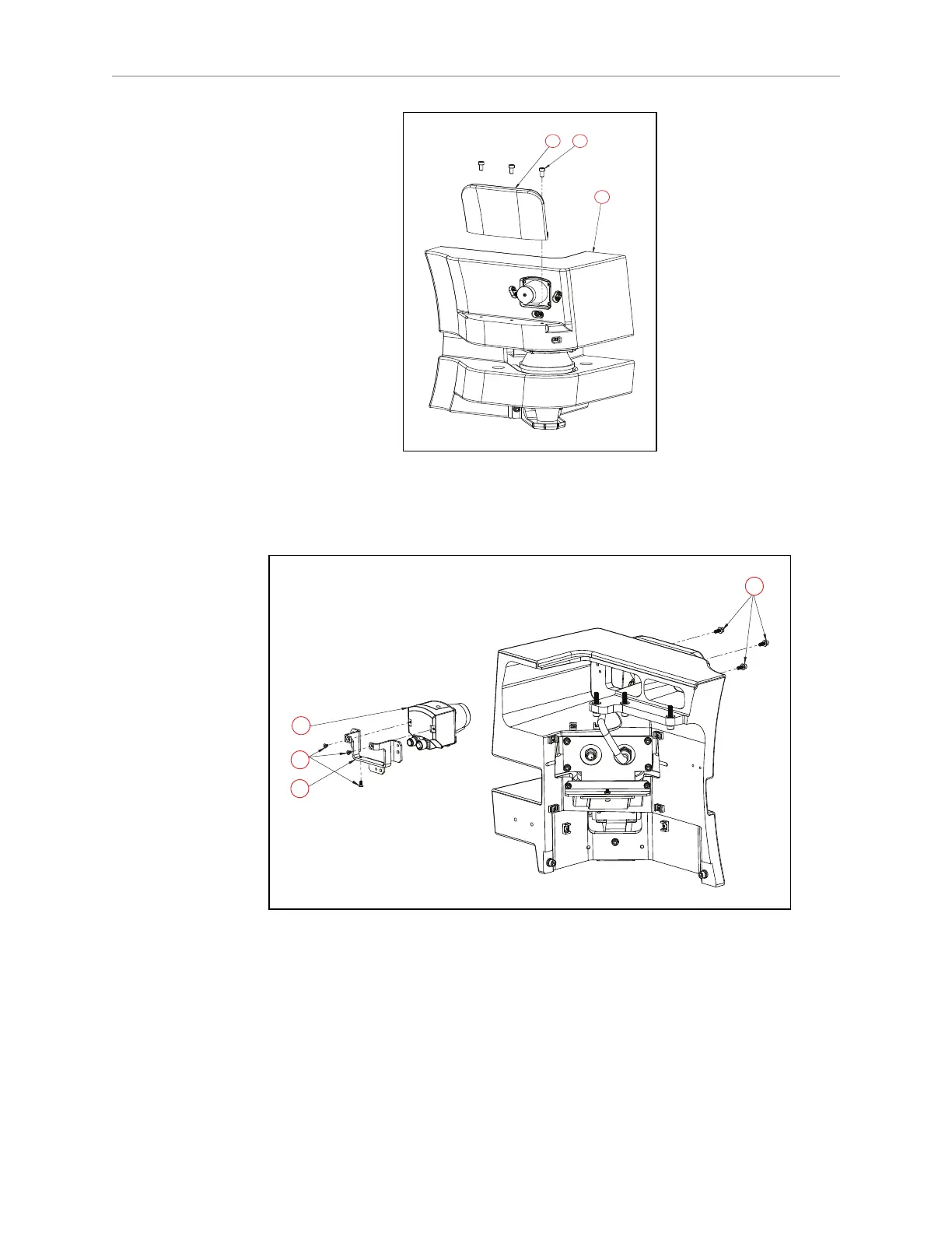
Figure 8-39. (A) Laser Corner, (B) M6 Screw, and (C) Laser Cover Fin
4.
Unscrew three M4 screws ((D) in Figure 8-39. ) that attach the side laser bracket to the
laser corner ((A) in Figure 8-39.
Figure 8-40. (A) Side Laser, (B)M3 Screw, (C) Laser Bracket, and (D) M4 Screw
5.
Next, unscrew the three M3 screws ((B) in Figure 8-39. ) that mount the bracket to the
side laser as shown in Figure 8-39.
Once the side laser is removed from the laser bracket, you may replace the side laser with a
new one or use the extension cable kit to relocate the side laser to your desired location.
Whether you install the power and data cables to the side laser before or after mounting it to
the new location, depends on your specific installation location on the payload structure.
31500-000 Rev A HD-1500 Platform User's Manual 248