01
nCreating
a
Project
File
The
following
descripton
provides
information
about
how
to
create
a
project
file
to
send
the
RUN
command
and
frequency
references
to
three
Inverters
and
read
the
Inverter
status.
(“PST”
indicates
the
WS01-PSTF1-J
Protocol
Support
Tool.)
First,
select
from
I/O
items,
monitor
items,
and
parameters
the
data
to
be
exchanged
according
to
the
applica-
tion.
Then
consider
what
sequence
is
required
by
using
the
protocol
macro
function.
Example:
Writes
control
input
items
(such
as
the
RUN
command
and
multi-function
input)
of
the
Inverter
and
frequency
reference,
monitors
the
control
output
(such
as
error
output
and
RUN
output)
of
the
Inverter,
and
monitors
the
Inverter
status.
Three
Inverters
with
Slave
addresses
from
01
to
03
are
installed
for
communications.
Checking
the
Register
Numbers
In
the
above
example,
the
following
three
registers
are
required.
Control
Input:
Register
0001
Hex
for
RUN
command
Frequency
Reference:
Register
0002
Hex
Control
Output:
Register
002C
Hex
for
Inverter
status
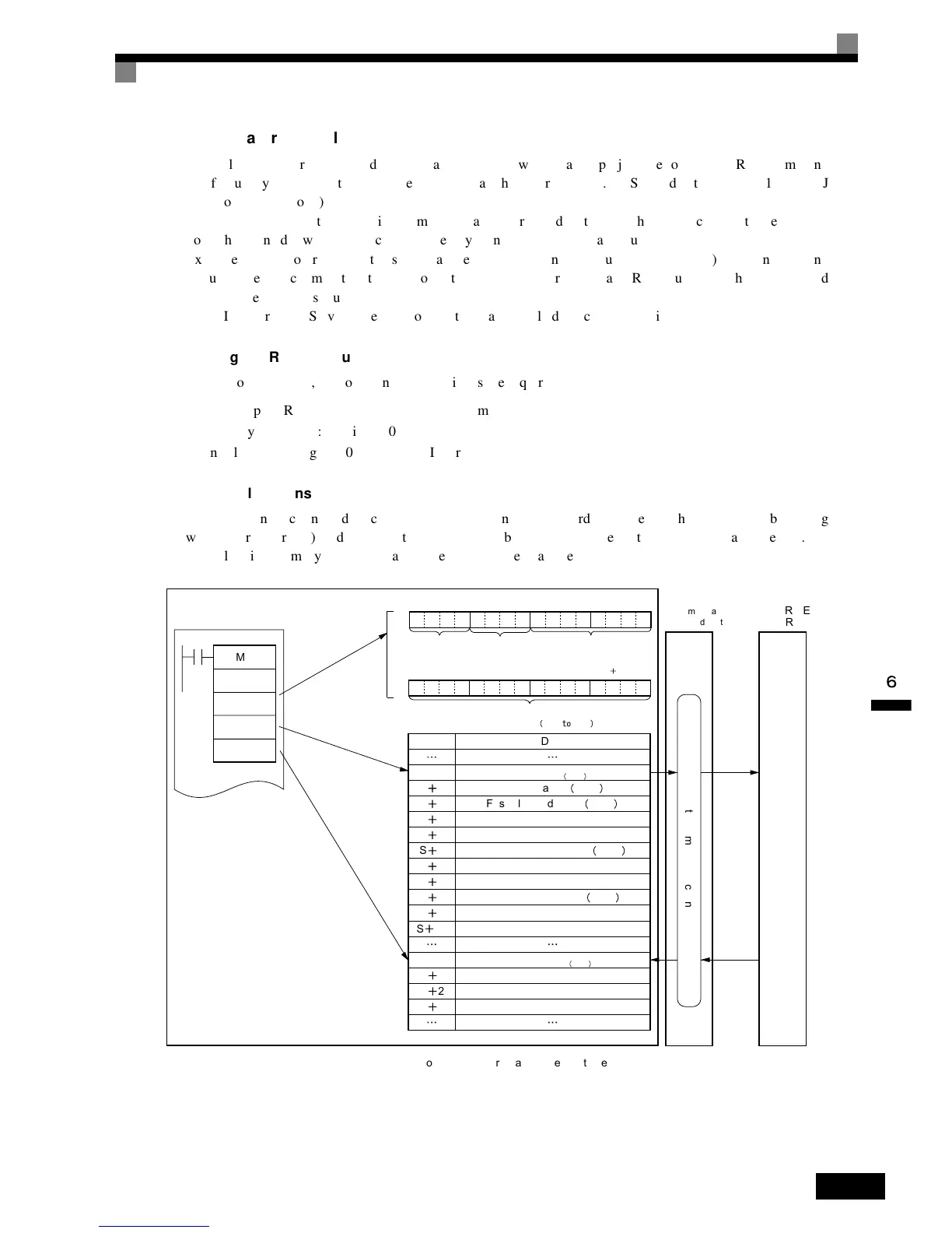
Memory
Allocations
The
PMCR
instruction
sends
each
Slave
the
data
in
consecutive
words
specified
by
the
operand
and
beginning
with
the
first
word
(S),
and
writes
in
the
memory
area
beginning
with
the
first
word
(D)
the
data
received.
The
following
memory
allocations
are
made
in
the
above
example.
SYSMAC CS or CJ-series Programmable Controllers
PMCR
SYSDRIVE
3G3RV
S
D
Communications
Board/Unit
Protocol macro function
Word Data
S
S
1
S
2
S
3
S
4
S
5
S
6
S
7
S
8
S
9
S
10
D
D
1
D
2
D
3
No. of Slaves 0003
First Slave address 0001
RUN command to Slave 1
Frequency reference to Slave 1
Second Slave address
0002
RUN command to Slave 2
Frequency reference to Slave 2
Third Slave address
0003
RUN command to Slave 3
Frequency reference to Slave 3
Slave 1 Inverter status
Slave 2 Inverter status
Slave 3 Inverter status
RS-422A
/485
C1
C2
Sequence No.
0000 to 03E7 Hex
000 999
Control data
Communica-
tions port
0 to 7 Hex
C1
C2
Serial port
Port 1: 1 Hex
Port 2: 2 Hex
Communications Board/Unit
number designation
Inner Board: E1 Hex
CPU Bus Unit: Unit No.
10 Hex
Number of data items sent in accordance with
PMCR instruction 000B
Number of data items received in accordance with
PMCR instruction 0003

 Loading...


