03
Sequence
number.
The
sequence
number
is
automatically
set.
Communication
Sequence
The
label
(name)
of
the
sequence.
Input
an
appropriate,
easy-to-distinguish
name.
Link
Word
Set
the
area
for
sharing
the
data
between
the
Programmable
Controller
and
Communications
Board.
In
this
example,
the
link
word
is
specified
by
the
operand
of
the
PMCR
instruction.
Therefore
no
link
word
is
set
here.
Control
Set
the
control
method,
such
as
flow
control.
Select
only
“modem
control”
for
communications
with
the
3G3RV.
Response
A
method
to
write
reception
data
to
the
I/O
memory
of
the
Programmable
Controller.
Select
“notify
by
scan”
for
communications
with
the
3G3RV.
Timer
Tr,
Timer
Tfr,
and
Timer
Tfs
Set
the
periods
to
monitor
the
transmission
and
reception
steps
with
timers
Tr,
Tfr,
and
Tfs.
The
following
tim-
ing
chart
shows
the
meaning
of
each
monitor.
Be
sure
to
set
the
periods
according
to
the
application.
The
step
will
be
retried
if
the
step
is
not
completed
within
the
monitor
periods.
An
error
will
occur
if
the
step
is
not
completed
within
the
monitor
time
again.
Set
a
period
of
approximately
0.5
s
each
for
communications
with
the
3G3RV.
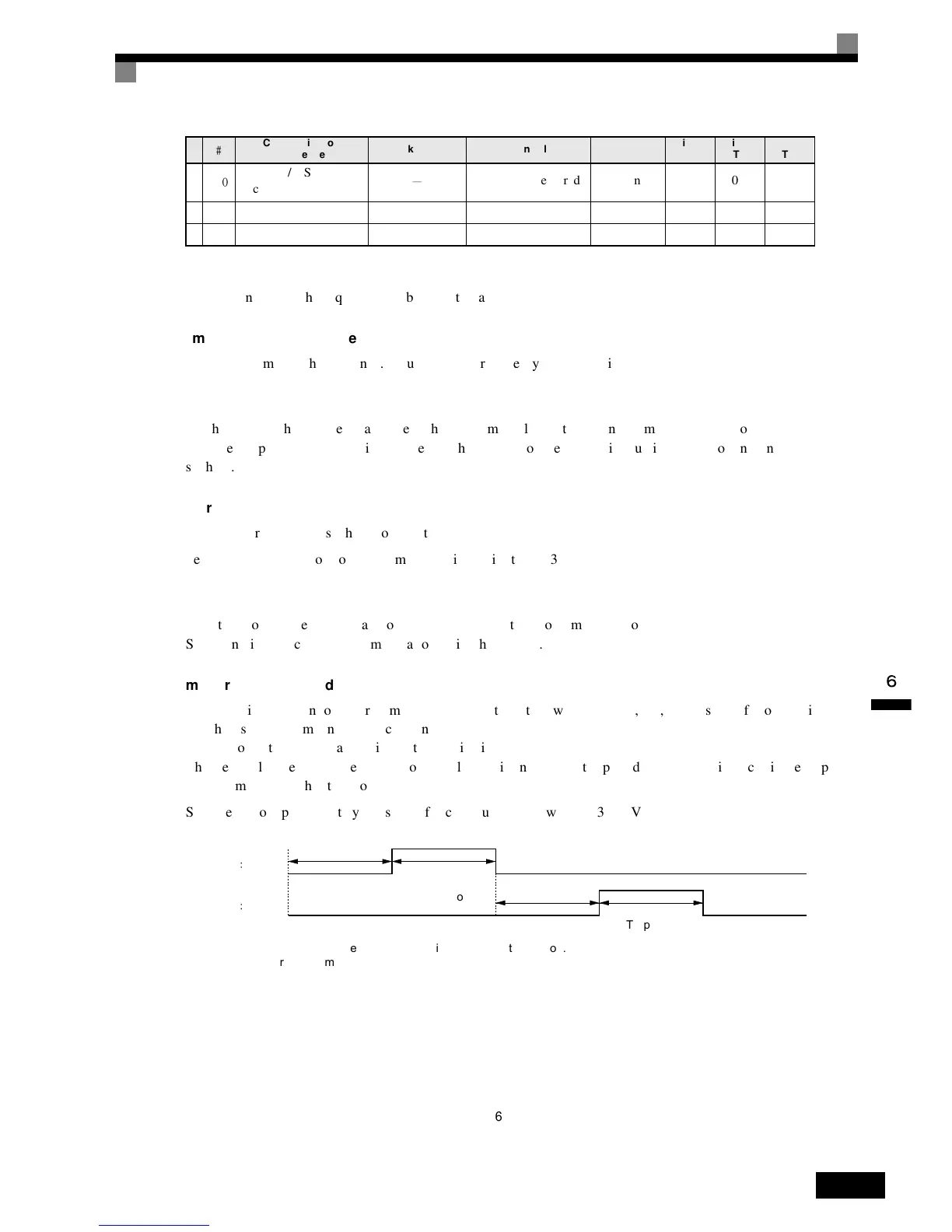
Fig 6.67
Communication
sequence
Link
word Control Response
Timer
Tr
Timer
Tfr
Timer
Tfs
Inverter
I/O
Send
&
Recv
Set
(Setting
required) Scan 0.5 0.5 0.5
Monitored for
Tfr period
Send & Recv Send
Recv
Ts
Monitored for
Tfs period
Ts: Send wait time set per step. Nothing is sent during this period.
Tfs: Monitors the completion of the data sent. If the data transmission is not finished within this period,
the data will be re-transmitted.
Tr: Monitors the response to be received. If the response is not returned within this period, the response will
be re-transmitted.
Tfr: Monitors the reception completion of the response. If the response transmission is not finished within this
period, the response will be re-transmitted.
Note If the Tr period is too long, the time to detect a communications error will be longer, during which the Inverter
cannot be controlled. Therefore, be sure to set an appropriate period.
Monitored for
Tr period

 Loading...


