EasyManua.ls Logo

Omron SYSDRIVE 3G3RV Series

Omron SYSDRIVE 3G3RV Series
446 pages
To Next Page IconTo Next Page
To Previous Page IconTo Previous Page
Loading...
1
0
-
16
F1-02
Operation
selection
at
PG
open
cir-
cuit
(PGO)
1 H1-04 Terminal
S6
function
selection
4
(3)
*8
F1-03
Operation
selection
at
overspeed
(OS)
1 H1-05 Terminal
S7
function
selection
6
(4)
*8
F1-04 Operation
selection
at
deviation 3 H2-01 Terminal
M1-M2
select 0
F1-05 PG
rotation 0 H2-02
Terminal
P1
function
select
(open
collector)
1
Terminal
M3-M4
function
select
(contact)
F1-06
PG
division
rate
(PG
pulse
moni-
tor)
1 H2-03
Terminal
P2
function
select
(open
collector)
2
Terminal
M5-M6
function
select
(contact)
F1-07
Integral
value
during
accel/decel
enable/disable
0 H3-01 Signal
select
terminal
A1
(voltage) 0
F1-08 Overspeed
detection
level 115 H3-02 Gain
(terminal
A1) 100.0
F1-09 Overspeed
detection
delay
time 1.0 H3-03 Bias
(terminal
A1) 0.0
F1-10
Excessive
speed
deviation
detec-
tion
level
10 H3-08
Multi-function
analog
input
termi-
nal
A2
signal
level
selection
2
F1-11
Excessive
speed
deviation
detec-
tion
delay
time
0.5 H3-09
Multi-function
analog
input
termi-
nal
A2
function
selection
0
F1-12 Number
of
PG
gear
teeth
10 H3-10Gain
(terminal
A2) 100.0
F1-13 Number
of
PG
gear
teeth
20 H3-11Bias
(terminal
A2) 0.0
F1-14 PG
open-circuit
detection
time 2.0 H3-12 Analog
input
filter
time
constant 0.00
F4-01 Channel
1
monitor
selection 2 H3-13 Terminal
A1/A2
switching 0
F4-02 Channel
1
gain 1.00 H4-01 Monitor
selection
(terminal
FM) 2
F4-03 Channel
2
monitor
selection 3 H4-02 Gain
(terminal
FM) 1.00
F4-04 Channel
2
gain 0.50 H4-03 Bias
(terminal
FM) 0.0
F4-05 Channel
1
output
monitor
bias 0.0 H4-04 Monitor
selection
(terminal
AM) 3
F4-06 Channel
2
output
monitor
bias 0.0 H4-05 Gain
(terminal
AM) 0.50
F4-07
Analog
output
signal
level
for
channel
1
0 H4-06 Bias
(terminal
AM) 0.0
F4-08
Analog
output
signal
level
for
channel
2
0
H4-07
Analog
output
1
signal
level
selec-
tion
0
F5-01 Not
used 0
F5-02 Not
used 1 H4-08
Analog
output
2
signal
level
selec-
tion
0
F5-03 Not
used 2 H5-01 Slave
address 1F
F5-04 Not
used 4 H5-02 Communication
speed
selection 3
F5-05 Not
used 6 H5-03 Communication
parity
selection 0
F5-06 Not
used 37 H5-04
Stopping
method
after
communi-
cation
error
3
F5-07 Not
used 0F H5-05
Communication
error
detection
selection
1
F5-08 Not
used 0F H5-06 Send
wait
time 5
F5-09 Not
used 0 H5-07 RTS
control
ON/OFF 1
F6-01
DeviceNet
fault
operation
selec-
tion
1 H6-01 Pulse
train
input
function
selection 0
F6-02
Communications
external
fault
input
detection
method
selection
0 H6-02 Pulse
train
input
scaling 1440
F6-03
Communications
external
fault
input
operation
selection
1 H6-03 Pulse
train
input
gain 100.0
F6-04 Not
used 0 H6-04 Pulse
train
input
bias 0.0
F6-05
Display
unit
selection
for
current
monitor
0 H6-05 Pulse
train
input
filter
time 0.10
H1-01 Terminal
S3
function
selection 24 H6-06 Pulse
train
monitor
selection 2
H1-02 Terminal
S4
function
selection 14 H6-07 Pulse
train
monitor
scaling 1440
H1-03 Terminal
S5
function
selection
3
(0)
*8
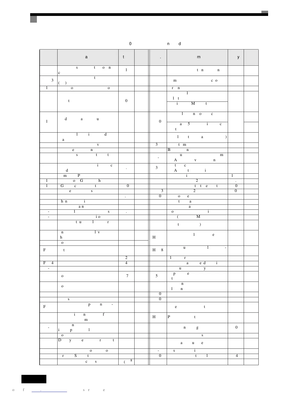
Table 10.1 Parameters (Continued)
No. Name
Fac-
tory
Setting
Set-
ting
No. Name
Fac-
tory
Setting
Set-
ting

Table of Contents

Related product manuals