52
n
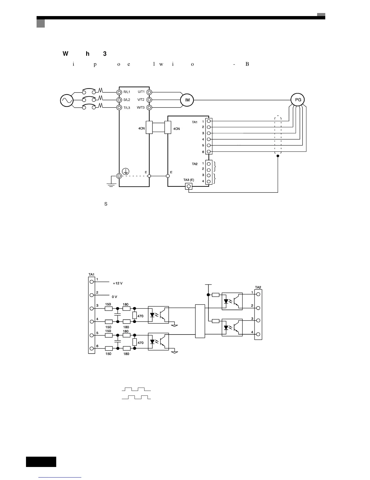
Wiring
the
3G3FV-PPGB2
Wiring
examples
are
provided
in
the
following
illustrations
for
the
3G3FV-PPGB2.
• Shielded twisted-pair wires must be used for signal lines.
• Do not use the pulse generator's power supply for anything other than the pulse generator (encoder).
Using it for another purpose can cause malfunctions due to noise.
• The length of the pulse generator's wiring must not be more than 30 meters.
• The direction of rotation of the PG can be set in parameter F1-05. The factory preset if for forward rota-
tion, A-phase advancement.
Fig 2.38 3G3FV-PPGB2 Wiring
•
When connecting to a voltage-output-type PG (encoder), select a PG that has an output impedance with
a current of at least 12 mA to the input circuit photocoupler (diode).
• The pulse monitor dividing ratio can be changed using parameter F1-06.
Fig 2.39 I/O Circuit Configuration of the 3G3FV-PPGB2
Three-phase 200
VAC (400 VAC)
Inverter
Power supply +12 V
Power supply 0 V
Power supply +12 V
A-phase pulse output (-)
Power supply +12 V
B-phase pulse output (-)
A-phase pulse monitor output
B-phase pulse monitor output
3G3FV-PPGB2
E6B2-CWZ6C
PG power
supply +12 V
A-phase pulse
input
B-phase pulse
input
A-phase
pulses
B-phase
pulses
Division rate circuit
B-phase pulse
monitor output
A-phase pulse
monitor output
A-phase pulses
B-phase pulses

 Loading...


