Internal Assemblies — Front Chassis 4: Repair
131
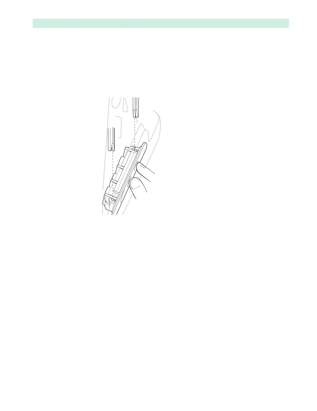
b Position the fork in your left hand, so that the rib faces the slot in the Front Chassis, and the
longer prong is closer to you.
c Starting with the longer prong of the fork, install the fork between the Front Chassis and Front
Case so that it locks the Measurement Module, see Figure 87.
d Engage the fork rib with the slot in the Front Chassis and secure with the M3x8 (T10) screw,
see Figure 85 on page 130.
e Tighten the screw to 6 inch-lb (0.7 N m).
5 Turn the device around on the working surface.
6 Position the CO
2
cable core in the stabilizer and secure with the M4x10 (T15) screw, see Figure 86,
inset.
7 Tighten the screw to 10 inch-lb. (1.1 N m).
8 Bend the CO
2
cable upward and connect to the Processor PCA CO
2
connector.
9 Reconnect the ECG Port to the Processor PCA.
10 If present, reconnect the SpO
2
Port to the SpO
2
PCA, see “SpO2 PCA” on page 126.
11 Ensure the connectors are fully seated.
12 If present, reconnect the NBP air tube to the NBP Port.
Thread the tube between the SpO
2
PCA (if present) and ECG Connector.
13 Reassemble and close the device. See “Closing the Case” on page 151.
To complete the replacement:
Run Performance Verification and Safety testing as described in the “Performance Verification”
chapter.
Figure 87 Measurement Module Installation