4: Repair Internal Assemblies — Front Chassis
130
Replacement
1 Inspect the tubing gasket on the perimeter of the face plate, see Figure 89 on page 133.
If the gasket is soiled, cracked, frayed, pinched, damaged in any other way, or developed a gap
between the tubing ends, then replace the gasket. See “Tubing Gasket Replacement” on page 96.
2 Position the Measurement Module so that the CO
2
Port is facing left, and the metal contacts of the
CO
2
cable connector face down toward the work surface.
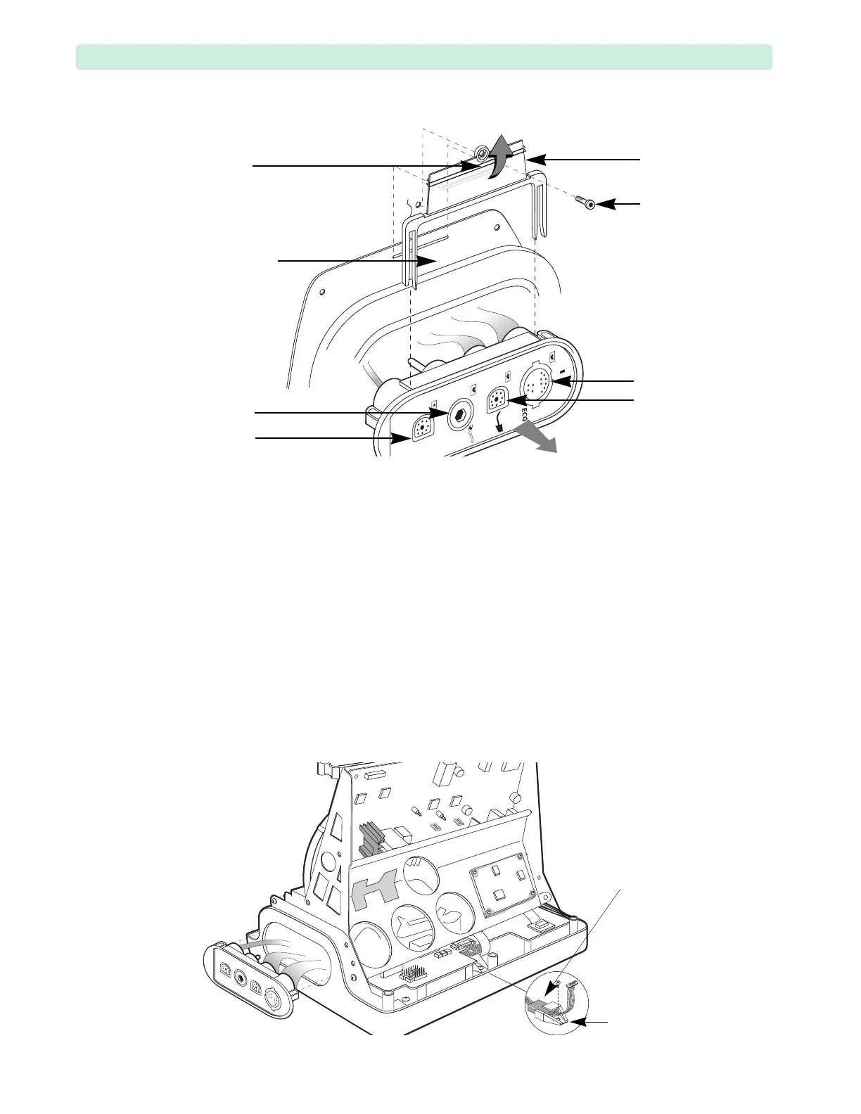
3 Gently slide the CO
2
cable under the Processor PCA, guiding it toward the Processor PCA CO
2
connector (see Figure 84 on page 129) and positioning the Measurement Module in the Front Case
opening.
4 Install the Measurement Module:
a Guide the Measurement Module with your right hand into the Front Case, and the flex circuits
in the Front Case opening, see Figure 86.
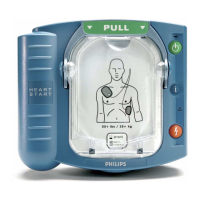
Figure 85 Measurement Module Assembly (with CO
2
) Removal
fork rib
NBP Port
(optional)
CO
2
Port
SpO
2
Port
(optional)
ECG Port
fork
fork rib lock
fork
screw
Figure 86 Positioning the CO
2
Cable