6Parts Flexible Module Server Parts
118
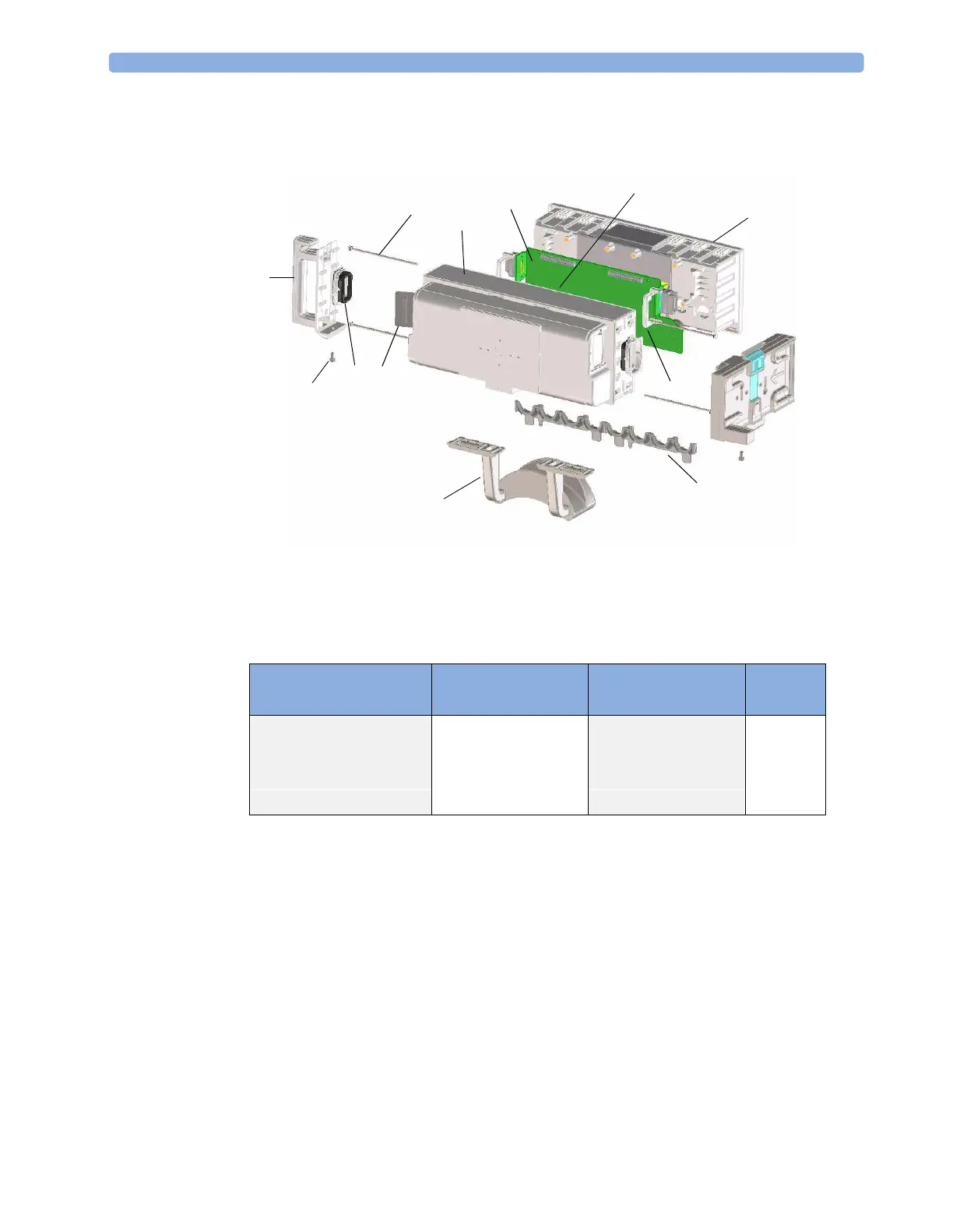
Flexible Module Server Parts
Figure 7 Flexible Module Server Parts
Exchange and Replacement Parts
2
4
3
3
3
3
3
3
4
1
3
3
Exchange Part Number Replacement Parts Description No. in
Diagram
M4041-68401 Mother board assembly 1
M8055-68401 CPU board assembly 2
M8048-64002 Small Parts kit 3
M8048-64001 Housing kit 4
 Loading...