Repairing the Anesthetic Gas Module 9 Anesthetic Gas Module
259
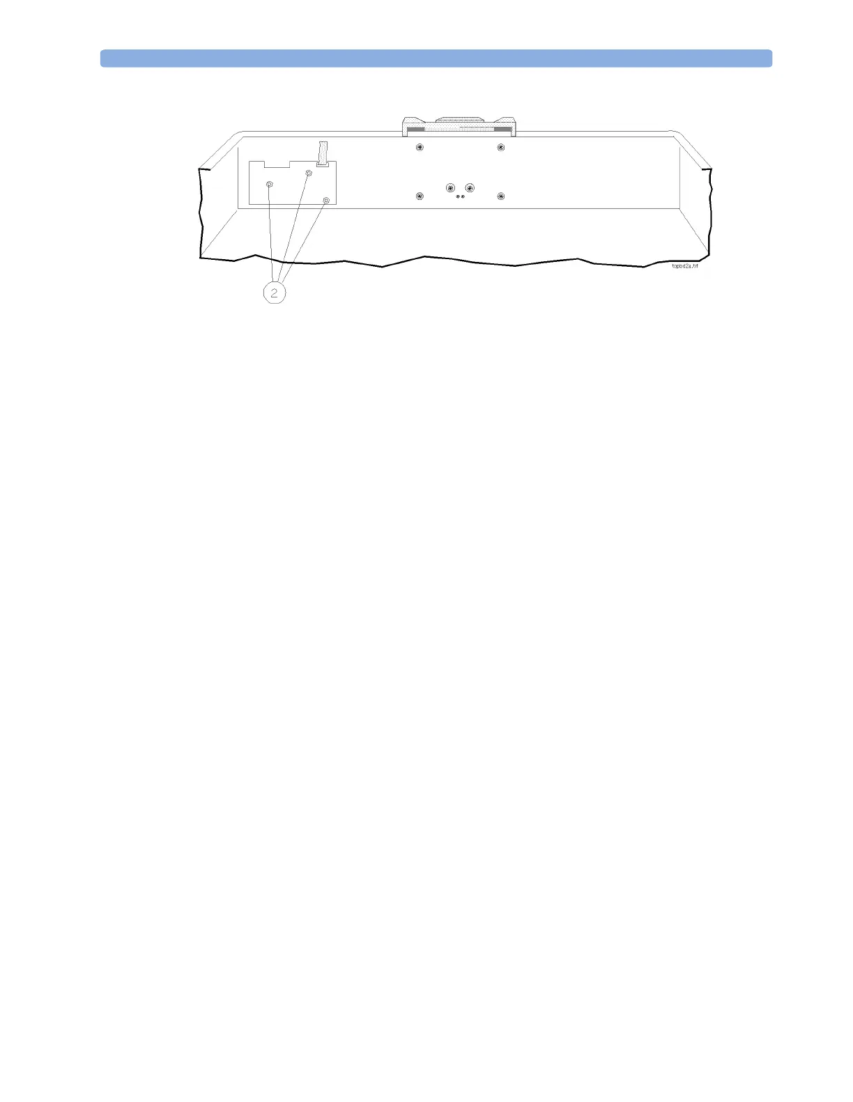
Figure 80 Removing the Top Cover PC Board
Watertrap Manifold and Protector
Removal
To remove the manifold and protector (refer to Figure 81):
1 Remove the top cover of the module.
2 Remove the Nafion tubing and purple connector tubing from the manifold connectors (1) on the
inside of the front cover.
3 Using a cross-tipped screwdriver, unscrew the 4 screws (2) securing the protector to the front cover
and remove the protector.
4 Using a cross-tipped screwdriver, unscrew the 2 screws (3) securing the manifold to the protector.
Replacement
To replace the manifold and protector (refer to Figure 81):
1 Using a cross-tipped screwdriver, replace the 2 screws securing the manifold to the protector.
2 Using a cross-tipped screwdriver, replace the 4 screws securing the protector to the front cover.
3 Replace the Nafion tubing and purple connector tubing onto the manifold connectors on the
inside of the front cover. Take care to attach the tubing with the red mark at the end to the
connector with the red marking (this indicates the “drainage” path). The gap between the end of
the nafion tubing and the manifold connectors (visible through the purple connector tubing) must
be less than 1mm.
Now perform the performance checks described “Test and Inspection Matrix” on page 262.
 Loading...