Repairing the Anesthetic Gas Module 9 Anesthetic Gas Module
253
NOTE After replacing the pump, check that all flat-cable connectors are firmly seated and show no signs of
damage.
5 Replace the top cover of the module.
Now perform the performance checks described in the “Test and Inspection Matrix” on page 262 and
reset the pump hours.
To reset pump hours, select
Reset Pump Hours from the Setup Gas Analyzer menu in the
monitor’s service mode. Confirm when prompted.
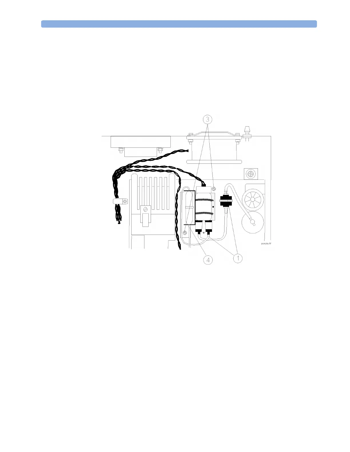
Figure 75 Replacing the Pump
Fan
Removal
To remove the fan (refer to Figure 76 and Figure 77):
1 Ensure that the Anesthetic Gas Module is switched off and isolated from the mains power supply.
Remove the top cover of the module.
2 Remove the power connector (1) from the main PC board.
3 Pry the twisted pair supplying power from the fan out of the cable clip (2).
4 Using a cross-tipped screwdriver, remove the four screws and washers (3) securing the fan and the
grill to the back panel of the module.
5 Remove the fan and connecting cable from the module.
 Loading...