9 Anesthetic Gas Module Repairing the Anesthetic Gas Module
262
Test and Inspection Matrix
The Test and Inspection Matrix describes:
• which tests need to be performed
• the expected test results
• what should be written by Philips service personnel on the Philips Installation Report or Customer
Service Order (CSO).
The second section When to Perform Test Blocks describes when the tests should be performed.
These tables should be followed for all installations and repairs.
NOTE The test procedures outlined for this test block are to be used only for verifying safe installation or
service of the product in question. The setups for these tests and the acceptable ranges or values are
derived from local and international standards but may not be equivalent. These are not a substitute for
local safety testing where it is required for an installation or service event.
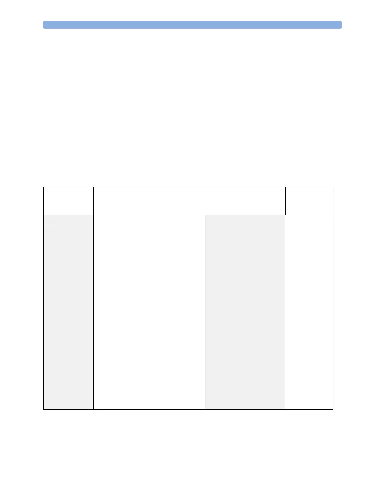
Test Bloc k Na m e Test or Inspection to be performed Expected Test Result What to Record
on Service
Record
Visual Check for any mechanical damage and all
external leads and accessories. Is the device
free of damage and are all accessories properly
set up?
Expected answer is "yes".
If so, visual test is passed.
V: P or
V: F
where P=Pass and
F=Fail
Power On Switch on the module. A built-in selftest and
communication test are running for two
minutes after "Power On". The green setup
LED near the power button indicates by
flashing if one of the tests failed. When tests
are successfully completed after 2 minutes the
LED is off and the AGM will enter warmup
mode (indicated by INOP
"GA.WARMUP").
Does AGM boot up successfully without
displaying any error or malfunction messages?
Expected answer is "yes". If so,
PowerOn test is passed.
PO: P or
PO: F
where P=Pass and
F=Fail
Performance
Leakage Check
Perform Leakage Check Measured flow value:
0-4 ml/min
PL: P or
PL: F
where P=Pass and
F=Fail
 Loading...