Repairing the Anesthetic Gas Module 9 Anesthetic Gas Module
247
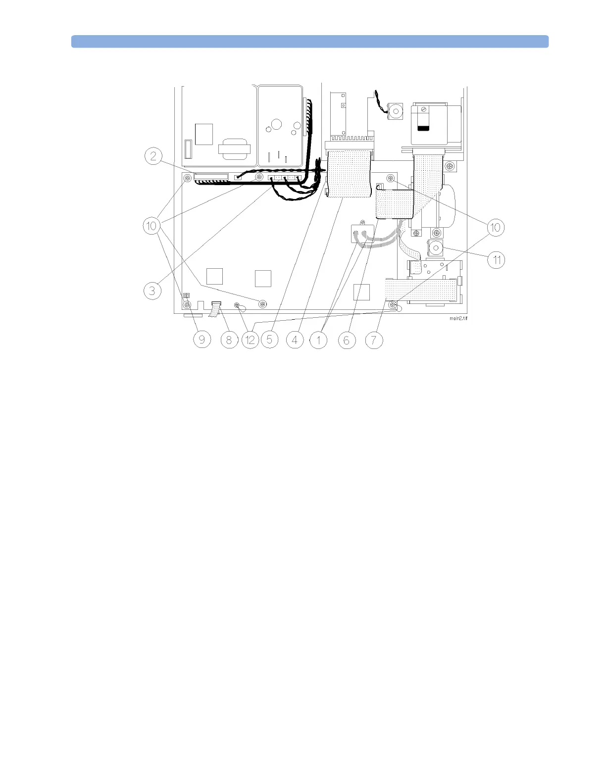
Figure 69 Removing the Main PC Board
O
2
Sensor
The O
2
sensor is always replaced together with the small PC board that controls it. The newer O
2
sensors have the board integrated inside the sensor housing.
Removal
To remove the O
2
sensor and its PC board follow the steps marked (a) and to remove the O
2
sensor
with integrated PC board follow the steps marked (b) (refer to Figure 70 and Figure 71):
1 Ensure that the module is switched off and isolated from the mains power supply. Remove the top
cover of the module.
2 Remove the 3 pneumatic connections (1) from the O
2
sensor.
3 Remove the flat cable connector (2) from the PC board that controls the O
2
sensor.
4 Remove the flat cable connector (2) from the connector on the top of the O
2
sensor housing.
5 Release the clips (3) securing the PC board to its mounting.
6 Using a cross-tipped screwdriver, remove the two screws and washers (4) securing the O
2
sensor to
its mounting brackets.
7 Carefully remove the O
2
sensor [(b) along with its PC board.]
NOTE If you are not operating O
2
, remove the appropriate jumper as described in “Jumpers” on page 103.
 Loading...