9 Anesthetic Gas Module Installation and Patient Safety
180
Making Connections to the AGM
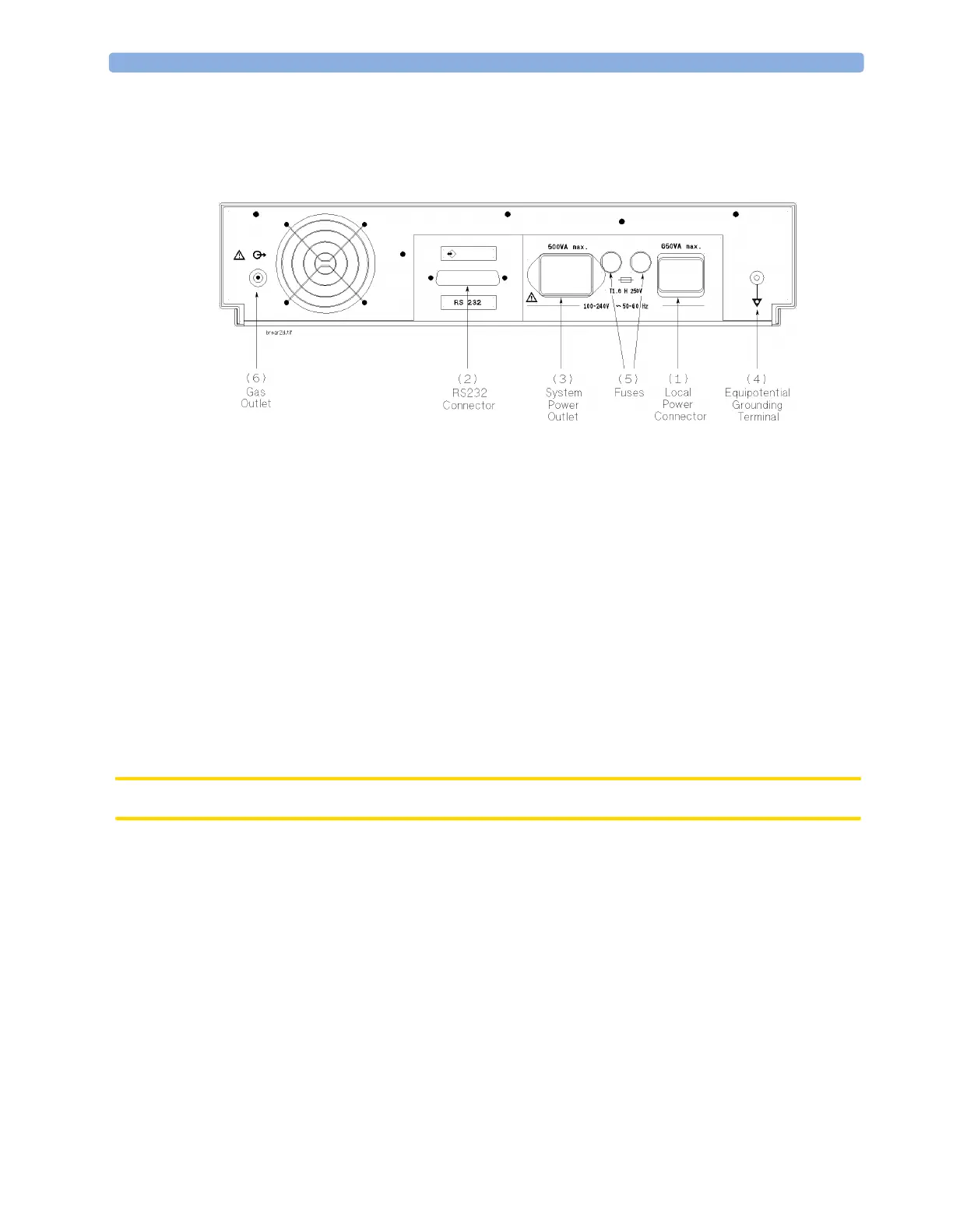
All connections to the AGM are made on its rear panel. Refer to Figure 36.
Figure 36 The Rear Panel
1 Local power connector; this is a 3-pin connector, used to connect the AGM to the local line
voltage supply.
The module can be operated from an ac power source of 100 - 240 V ± 10%, 50/60 Hz. The
adjustment is made automatically by the power supply inside the module.
2 RS232 Connector (RS232 Interface); this is a 25-pin “D” type connector, used to connect the
AGM to the lower RJ45 connector of the monitor (Slot 04, MIB Devices - see Installation
Instructions).
The connection can be made with the following cables:
– M1026A#K11 1 m (M1026-61001)
– M1026A#K12 3 m (M1026-61002)
– M1026A#K13 10 m (M1026-61003)
3 System power outlet (restricted use); this can be used to output power to the monitor
CAUTION The system power outlet may not be used with any other devices.
4 Equipotential Grounding Terminal; this is used to connect the AGM to the hospital’s grounding
system.
5 Line protection fuses, T1.6 H 250V.
6 Anesthetic gas exhaust. If N
2
O and/or other inhalation anesthetics are used during anesthesia,
pollution of the operating room should be prevented. Once the gas sample has passed through the
AGM, it should either be returned to or removed from the anesthesia circuit.
Sample Gas Connections to the Gas Exhaust
Returning the Gas Sample
You will need the following equipment to return the gas sample to the anesthesia circuit:
MONITOR
 Loading...