Introduction 9 Anesthetic Gas Module
173
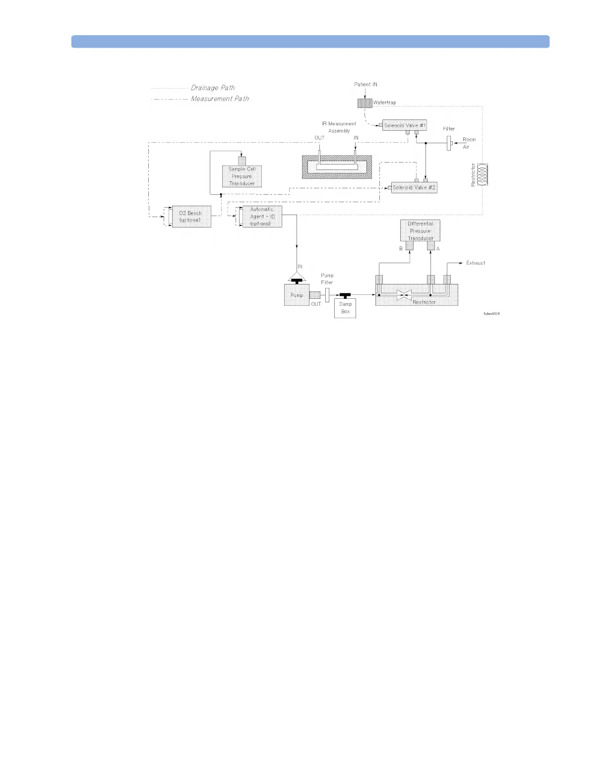
Figure 31 Pneumatic System
The pneumatic system works in the following way:
1 Eliminates residual water and fluids from patient sample gas using the watertrap and eliminates
water vapor using Nafion Tubing.
2 Splits the patient’s sample gas flow (150ml/min) into the measurement path (120ml/min) and
drainage path (30ml/min).
3 Passes the patient’s sample gas in the measurement path at 120ml/min through the measurement
benches.
4 Delivers zero calibration gas to the sample cells for the periodic zeroing.
5 Exhausts the patient’s sample gas, the zero calibration gas, and the span calibration gas.
6 Monitors for an occlusion in the sampling pneumatics.
Pump
The servo-controlled pump is attached to the exhaust of the Anesthetic Gas Module. It generates the
flow through the system and pulls the gas from the airway adapter through the measurement
subsystems to the exhaust outlet. It also delivers the zero calibration gas to the sample cells of the
measurement subsystems for the periodic zero procedures and it exhausts the patient’s sample gas, the
zero calibration and field calibration gases.
The flow-rate control logic drives the pump as hard as necessary to maintain the selected flow rate. A
partial occlusion or an inefficient pump results in the pump being driven harder. A serious occlusion
results in the pump being driven at or near its maximum load. This triggers a sensing circuit, which
then reports an occlusion.
 Loading...