7 Installation Instructions Installing the Monitor (M8005A or M8007A)
138
Connections
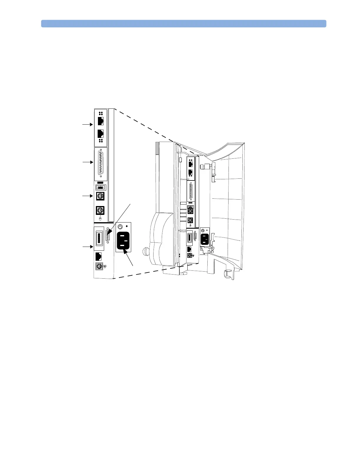
The following figure is a side view of the monitor, and shows the cable and interface board
connections.
All molded connector cables on the monitor side attach at the location shown in the figure. The device
may have a second MSL port on the same side as the power switch near the ECG out location (not
shown in this figure).
Figure 18 MP60/MP70 Cable and Interface Board Connections
LAN
LAN
X
=
DCC
DCC
X=
DCC DCC
Parallel
Slot 04
MIB Devices
Slot 03
Printer
Slot 02
Keyboard/Mouse
Slot 01
MSL
Wired
Wireless
Power
Video
 Loading...