9 Anesthetic Gas Module Installation and Patient Safety
178
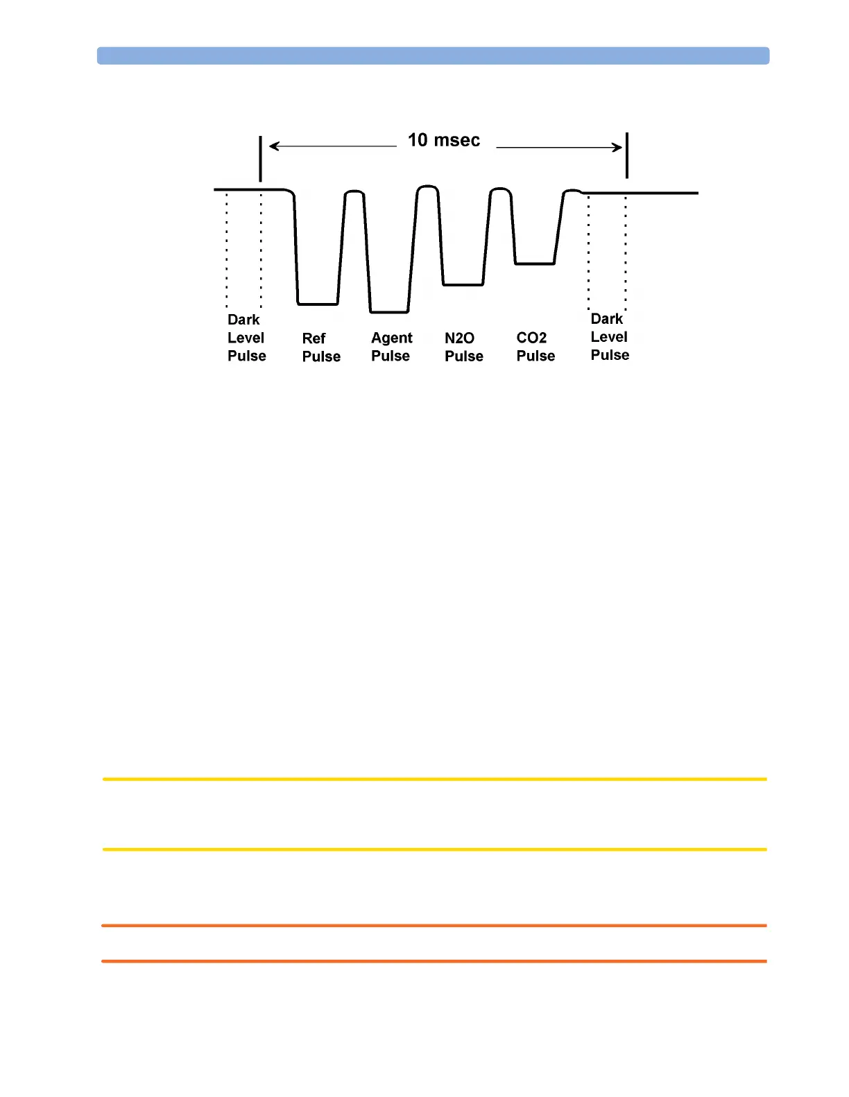
Figure 34 IR Detector Output Signal
Installation and Patient Safety
This chapter describes how to install the Philips M1026A Anesthetic Gas Module. It details the
operating environment required by the Philips M1026A Anesthetic Gas Module as well as instructions
on how to affix the local language labels and physically connect it to the monitor. Next, the patient
safety information is detailed. Finally, this chapter describes the software setup required and any post-
installation checks that have to be performed before using the Philips M1026A Anesthetic Gas Module
together with a reminder of the preventive maintenance (PM) checks and their frequencies.
Where post-installation procedures are specific to installation, they are described in full in this chapter.
For procedures which are also used in other situations (for example calibration, preventative
maintenance, etc.), a reference to the description will be given.
Physical Installation
This section describes the operating and storage environment for the Philips M1026A Anesthetic Gas
Module, affixing the local-language labels, connecting to the monitor, and fitting the gas exhaust
return system.
CAUTION The Philips M1026A Anesthetic Gas Module must be positioned horizontally on a level surface. To
avoid condensed water collecting in the patient sample tube, it is recommended that the Philips
M1026A Anesthetic Gas Module is positioned at or above patient level, wherever possible.
Environment
WARNING Possible explosion hazard if used in the presence of flammable anesthetics.
 Loading...